
Velocity and displacement mixed locker and velocity and displacement mixed locking method

A locker and displacement technology, applied in bridge parts, bridges, building components, etc., can solve the problems of reducing the volume and cost of the unit locking force, and achieve the effect of simple structure, strong applicability, volume and cost reduction

Active Publication Date: 2017-07-14
ZHUZHOU TIMES NEW MATERIALS TECH
View PDF7 Cites 7 Cited by
  • Summary
  • Abstract
  • Description
  • Claims
  • Application Information

AI Technical Summary

Problems solved by technology

The above existing technologies all need to be further improved in terms of reducing the volume and cost of the unit locking force

Method used


Image

  • Velocity and displacement mixed locker and velocity and displacement mixed locking method
  • Velocity and displacement mixed locker and velocity and displacement mixed locking method

Examples


Embodiment Construction

[0028] The present invention will be described in detail below in conjunction with the accompanying drawings and embodiments.

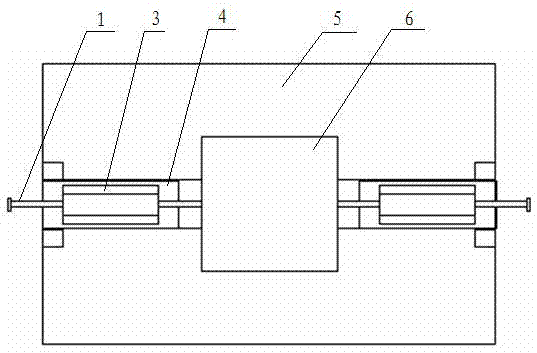
[0029] Please refer to figure 1 , figure 2Among them, the speed-displacement hybrid locker (locking device) is designed as a left-right symmetrical structure, mainly composed of a sliding body 6, a locking block 4, a safety pin 2, a fixed body 5 and a one-way damper, and the one-way damper includes a piston rod 1 And cylinder block 3, wherein lock block, safety pin, one-way damper all have two left and right symmetry. The sliding body 6 can relatively slide on the fixed body 5 . One end of the one-way damper is connected to the sliding body through the piston rod 1, and can slide relative to the cylinder body 3 under the thrust of the sliding body. The one-way damper is fixed on the sliding body in a cantilever manner through the piston rod, and the corresponding locking block 4 under the piston rod is slotted to ensure that the locking block is n...


PUM


Abstract

The invention discloses a velocity and displacement mixed locker and a velocity and displacement mixed locking method. The velocity and displacement mixed locker is a bilaterally symmetric structure and comprises a fixed body, a sliding body, a one-way damper, a locking block and a safety pin; one end of the one-way damper is connected with the sliding body through a piston rod; the locking block is arranged on the fixed body; the locking block is connected with the fixed body through the safety pin; and a cylinder body is mounted on the locking block. When the sliding body and the fixed body slide relative to each other at a velocity lower than a preset value, the safety pin is not cut off and the locking block does not execute locking; and when the sliding body and the fixed body slide relative to each other at a velocity larger than the preset value, the safety pin is cut off and the locking block executes locking so as to provide a locking force larger than a damping force; therefore, a purpose of velocity and displacement combined locking is achieved. The velocity and displacement mixed locker has the advantages that the velocity and displacement mixed locker is simple and reliable; the applicability of the velocity and displacement mixed locker is strong; the provided locking force is larger than the locking force provided by the one-way damper; and the velocity and displacement mixed locker realize stressed self-locking in the sliding direction of the sliding body.

Description

technical field [0001] The invention relates to the technical field of bridges and buildings, in particular to a support and a device that has a sliding function and needs to distinguish the sliding speed and select fast sliding for sliding locking. Background technique [0002] The damper is a component whose main body is a piston-type cylindrical cavity structure. Through the special performance "speed sensitivity" of the high-viscosity fluid filled in the cavity in the piston, a gap between the cylinder and the piston is generated under low-speed working conditions. The damping force is very small, and as the speed increases, the damping force rapidly rises to the design value, and the damper changes from flexible to rigid and close to "locking", realizing the relative displacement at low speed and the limit at high speed between the connecting members at both ends. bit function. The one-way damper used in the present invention is to add a one-way valve in the ordinary d...

Claims


Application Information

Patent Timeline
Patent Type & Authority Applications(China)
IPC IPC(8): E01D19/00E04B1/98
CPCE01D19/00E04B1/98
Inventor 李世珩夏俊勇封溢韩鹏飞宁响亮郭红锋桂长忍
Owner ZHUZHOU TIMES NEW MATERIALS TECH
Learn More