Efficient foot-bottom replacement mechanism for foot-type robot

A robot and sole technology, applied in the field of robotics, can solve the problems of the harsh and changeable service environment of foot robots, the sole structure is difficult to meet the adhesion requirements, and the card slot is easy to invade gravel and soil, etc., so as to improve the rapid adaptability , Improving environmental adaptability and preventing the intrusion of impurities

Active Publication Date: 2017-07-14
DALIAN UNIV OF TECH
View PDF4 Cites 0 Cited by
  • Summary
  • Abstract
  • Description
  • Claims
  • Application Information

AI Technical Summary

Problems solved by technology

The service environment of legged robots is harsh and changeable, and a single sole structure is difficult to meet the adhesion requirements of all surfaces. In order to adapt to different surface environments, it is necessary to replace soles with different structures. An efficient sole replacement mechanism is needed to improve the performance of legged robots. environmental adaptability
The existing sole replacement mechanism is too simple and the replacement efficiency is not high. It is urgent to design an efficient sole replacement mechanism
[0003] The patent publication number is CN104973157A, and the inventor Wang Fuji et al. disclosed a foot replacement mechanism in the invention patent "A Foot-type Robot Foot Quick-change Mechanism", which adopts slots and buckles, grooves and ribs, and The positioning pin realizes the replacement and locking of the sole. The unlocking process is inconvenient and has no protection ability. In harsh environments, the card slot is easy to invade gravel, mud and other impurities, which affects the replacement of the sole.

Method used


Image

  • Efficient foot-bottom replacement mechanism for foot-type robot
  • Efficient foot-bottom replacement mechanism for foot-type robot
  • Efficient foot-bottom replacement mechanism for foot-type robot

Examples


Embodiment Construction

[0011] The specific implementation of the present invention will be described in detail below in conjunction with the accompanying drawings and technical solutions.

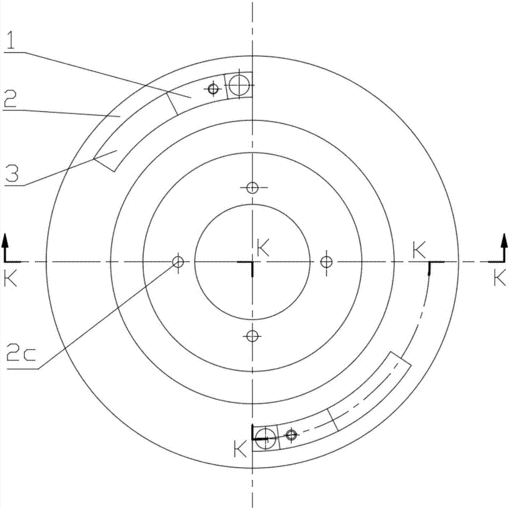
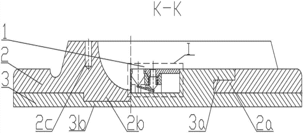
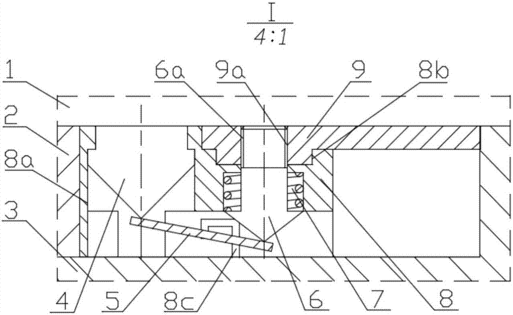
[0012] The high-efficiency foot robot foot replacement mechanism consists of two quick-change lock assemblies 1, a foot base 2 and a foot plate 3, such as figure 1 shown. The foot end base 2 has two slots 2a distributed symmetrically in the circumferential direction, a boss 2b at the bottom, and four threaded holes 2c uniformly distributed circumferentially at the top. Two buckles 3a are symmetrically distributed in the circumferential direction of the sole plate 3, and there is a pit 3b in the middle. The card slot 2a of the foot end base 2 cooperates with the buckle 3a of the sole plate 3, the boss 2b cooperates with the recess 3b, and the quick-change lock assembly and the card slot 2a have an interference fit, such as figure 2 shown. Quick change lock assembly 1 is made up of switch button 4, lever gasket...


PUM


Abstract

The invention relates to an efficient foot-bottom replacement mechanism for a foot-type robot and belongs to the technical field of robots. The replacement mechanism is composed of a foot end base, two quick lock changing assemblies and a foot bottom plate; clamping grooves are formed in the foot bottom plate and matched with clamping buckles on the foot bottom plate to achieve foot bottom connection; the quick lock changing assemblies are assembled on the foot end base in an interference fit mode; and lock covers seal the clamping grooves while achieving locking. Each quick lock changing assembly is composed of a shell body, a switch button, the locking cover, a lock cover screw column, a spring and a lever gasket. Efficient locking and unlocking of the foot-bottom replacement mechanism are achieved through the quick lock changing assemblies, meanwhile, impurity intrusion is prevented, and safety and reliability of the replacement mechanism is guaranteed. According to the mechanism, the overall structure is compact, using is convenient and quick, the protective function is achieved, efficient foot bottom replacement can be achieved in the harsh environment, and the environment adaptability of the foot-type robot is improved. Using is safe and reliable, the foot bottom can be quickly replaced, and the quick adaptability of the foot-type robot is improved.

Description

technical field [0001] The invention belongs to the technical field of robots, and relates to a sole replacement mechanism of a legged robot. Background technique [0002] Legged robots have many characteristics such as discrete footholds, active vibration isolation, and strong adaptability to surface conditions, which make them have the potential to be widely used in various complex surface environments. The service environment of legged robots is harsh and changeable, and a single sole structure is difficult to meet the adhesion requirements of all surfaces. In order to adapt to different surface environments, it is necessary to replace soles with different structures. An efficient sole replacement mechanism is needed to improve the performance of legged robots. environmental adaptability. The existing sole replacement mechanism is too simple, and the replacement efficiency is not high, so it is urgent to design an efficient sole replacement mechanism. [0003] The paten...

Claims


Application Information

Patent Timeline
Patent Type & Authority Applications(China)
IPC IPC(8): B62D57/032
CPCB62D57/032
Inventor 马建伟邹有阳王福吉张洪梅贾振元尹宏俊周黎明徐震宇
Owner DALIAN UNIV OF TECH
Why Eureka
Try Eureka