Spun yarn winding system

A kind of equipment and spinning technology, which is applied in the production of complete sets of equipment for artificial threads, filament production, textiles and papermaking, etc., and can solve problems such as delays in the end of hanging silk

Active Publication Date: 2017-07-11
TMT MACHINERY INC
View PDF9 Cites 7 Cited by
  • Summary
  • Abstract
  • Description
  • Claims
  • Application Information

AI Technical Summary

Problems solved by technology

In this case, in order to avoid interference between the thread-hanging robot and the operator or device that is collecting the package, it is necessary to wait for the completion of the package recovery before moving the thread-hanging robot to the destination winding machine, etc. will delay

Method used


Image

  • Spun yarn winding system
  • Spun yarn winding system
  • Spun yarn winding system

Examples


Embodiment Construction

[0059] Hereinafter, preferred embodiments of the present invention will be described.

[0060] (Overall configuration of spinning winding equipment)

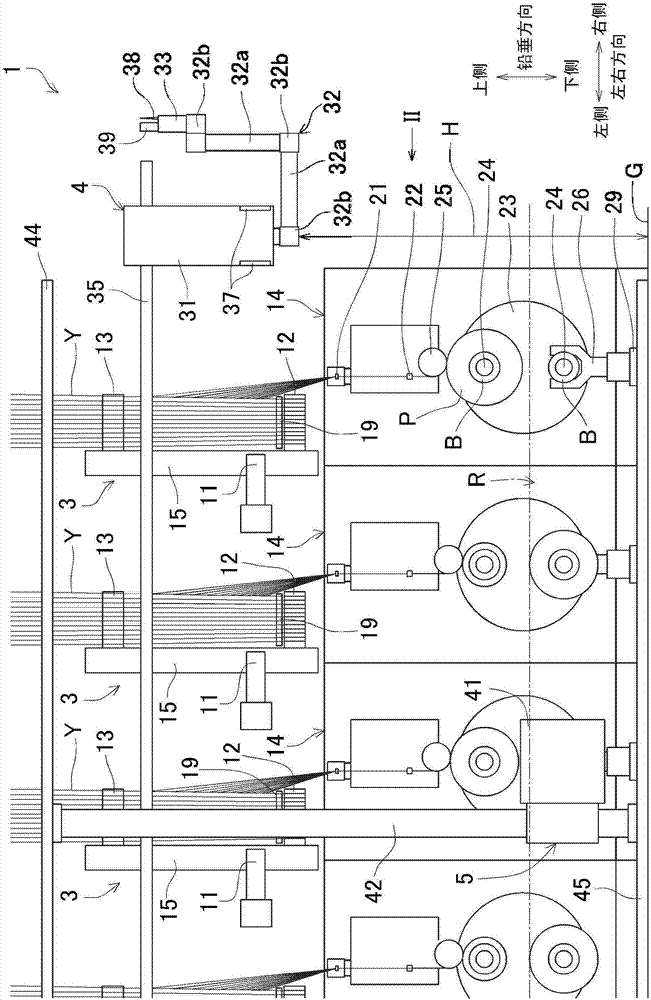
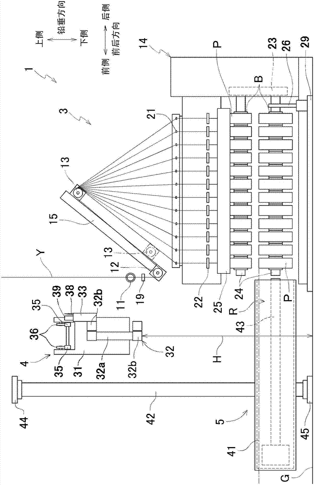
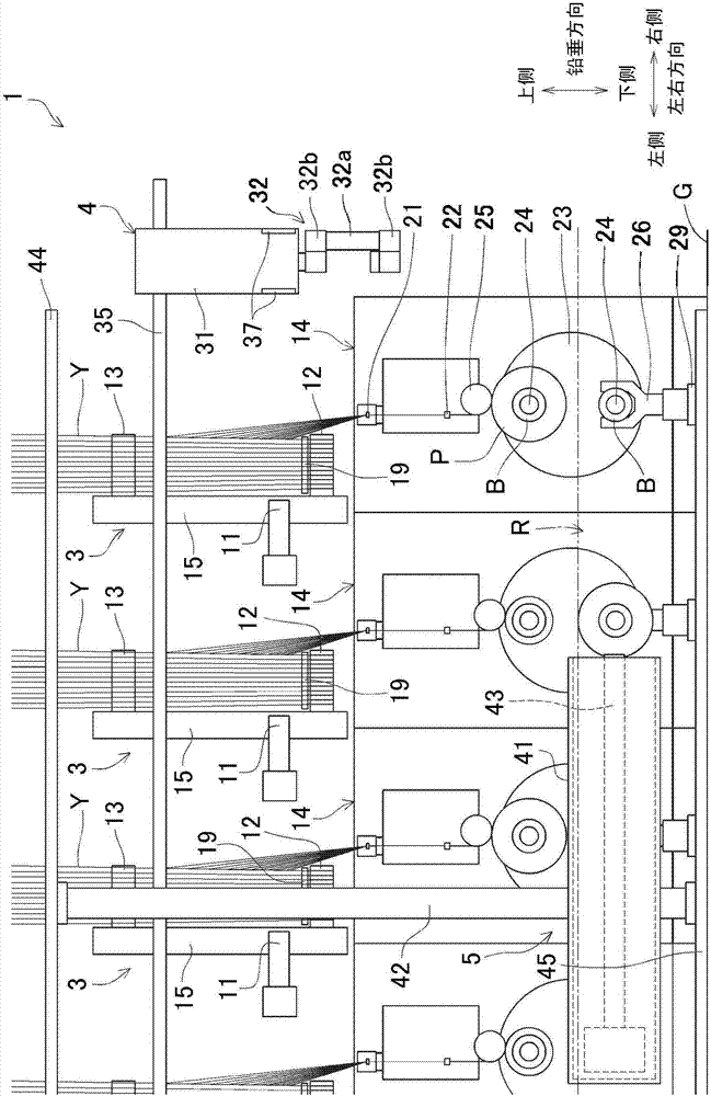
[0061] The spinning winding device 1 of the present embodiment draws a plurality of yarns Y spun from a spinning device (not shown), and winds them on a plurality of bobbins B to form a plurality of packages P. Such as Figure 1 ~ Figure 4 As shown, the spinning winding equipment 1 includes a plurality of pulling units 3 , a spinning robot 4 and a package collecting device 5 provided in common with the plurality of pulling units 3 .

[0062] A plurality of traction units 3 are arranged along one horizontal direction. In addition, in the following, the direction in which a plurality of traction units 3 are arranged is referred to as the left-right direction (the "second direction" in the present invention), and the direction that is horizontal and perpendicular to the left-right direction is referred to as the front-rear direct...


PUM


Abstract

In a spun yarn winding system, a yarn threading robot is less likely to interfere with an operator or an apparatus which collects packages. Take-up units 3 are lined up in the left-right direction. Each take-up unit 3 is configured to take up yarns Y spun out from a spinning apparatus and form packages by winding the yarns Y into bobbins B. A yarn threading robot 4 is provided above a winding unit 14 of the take-up unit 3, and hangs down from a guide rail 35 extending in the left-right direction over the take-up units 3 and moves in the left-right direction along the guide rail 35. At least when moving along the guide rail 35, the yarn threading robot 4 is positioned above the upper end of a fully-wound package P attached to a bobbin holder 24.

Description

technical field [0001] The present invention relates to a spinning winding device, which winds a plurality of filaments spun from a spinning device. Background technique [0002] In the spinning winding device described in Patent Document 1, a plurality of yarns spun from a spinning machine are wound around first and second godet rolls. And, the plurality of wires are respectively hung on a plurality of traverse fulcrum guides. Then, each yarn traverses through the traverse guide with the traverse fulcrum guide as a fulcrum, and is wound around the bobbin attached to the bobbin holder. In addition, in Patent Document 1, in order to hang a plurality of yarns spun from a spinning machine to a spinning winding device, first, the second godet roller is moved to the yarn hanging position, whereby the first The godet roll approaches the second godet roll, and the plurality of traverse fulcrum guides approach each other by moving the plurality of traverse fulcrum guides toward th...

Claims


Application Information

Patent Timeline
Patent Type & Authority Applications(China)
IPC IPC(8): D01D10/04D01D11/00
CPCD01D10/0481D01D11/00B65H54/88B65H57/003B65H67/048D01D13/02B65H2701/3132
Inventor 日置雅明辻本明彦
Owner TMT MACHINERY INC
Why Eureka
Try Eureka