Test fixture for simply supported beam fatigue loading and use method of test fixture

A fatigue loading and test fixture technology, applied in measuring devices, instruments, scientific instruments, etc., can solve the problems of high cost and long fatigue test time, achieve easy loading and unloading, reduce time and cost consumption, and ensure accuracy. Effect

Pending Publication Date: 2017-07-07
SHENYANG JIANZHU UNIVERSITY
View PDF0 Cites 10 Cited by
  • Summary
  • Abstract
  • Description
  • Claims
  • Application Information

AI Technical Summary

Problems solved by technology

[0005] Aiming at the above-mentioned technical problems of conventional fatigue tests such as long test time and high cost, the present invention provides a test fixture for fatigue loading of simply supported beams and a method for using the same. Vibration motors are used as the fatigue loading equipment. While providing the fatigue load requirements, it can ensure that the initial position of the simply supported beam remains unchanged, effectively position and clamp the simply supported beam, ensure the progress of the fatigue test, and facilitate the observation of the damage of the test piece

Method used


Image

  • Test fixture for simply supported beam fatigue loading and use method of test fixture
  • Test fixture for simply supported beam fatigue loading and use method of test fixture
  • Test fixture for simply supported beam fatigue loading and use method of test fixture

Examples


Embodiment

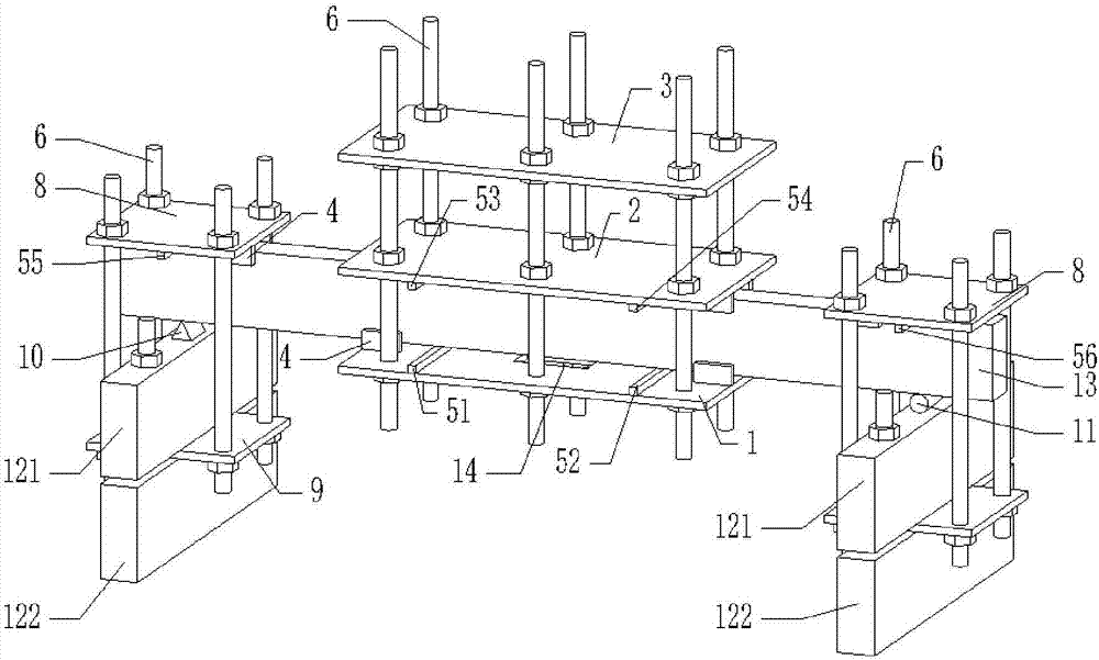
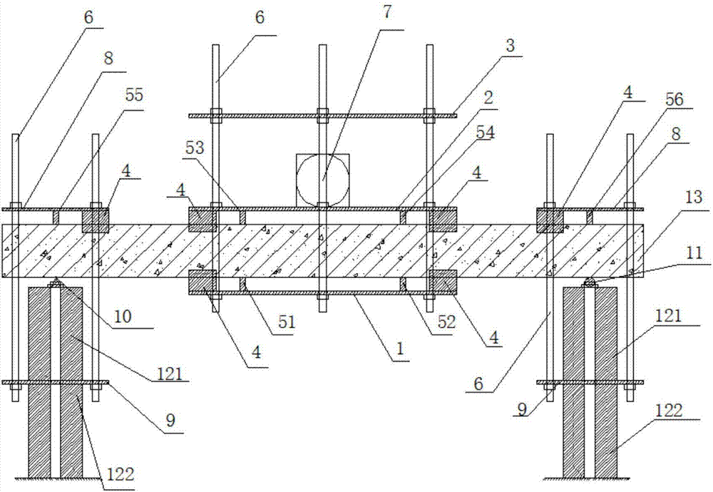
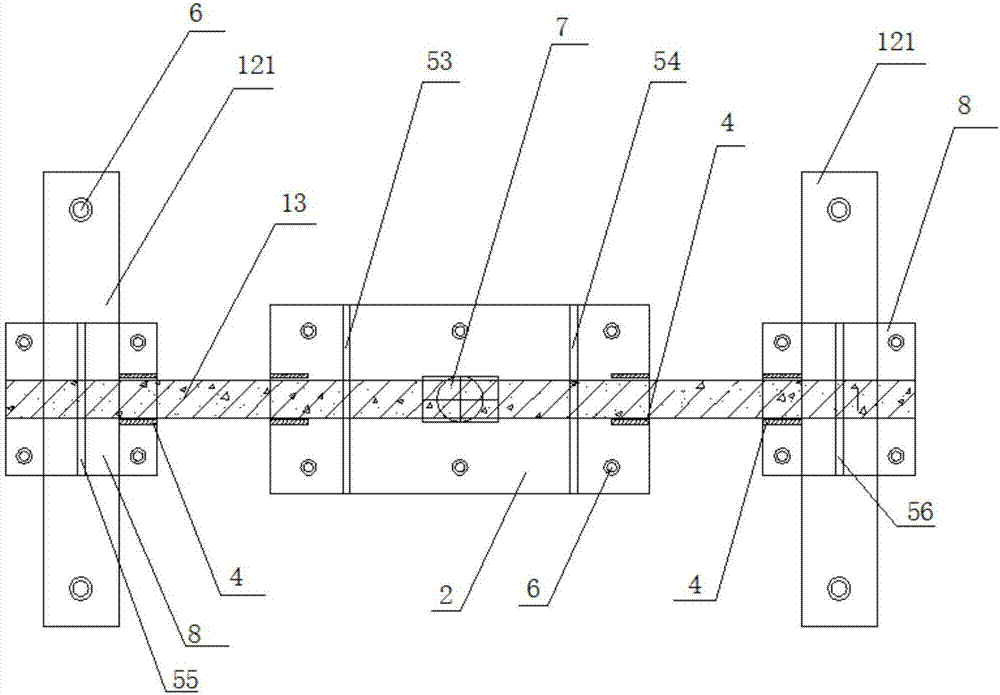
[0043] Example: such as Figure 1-Figure 9 As shown, a test fixture for fatigue loading of simply supported beams in the present invention includes fixture I arranged at the mid-span of simply supported beam 13, fixture II and vibration motor 7 arranged at both ends of simply supported beam 13, as Figure 4As shown, the clamp I includes fastening plates I1, fastening plates II2, screw nuts, splints 4 and load ribs 51, 52, 53 and 54 placed on the upper and lower sides of the simply supported beam 13. The fastening plates I1 It is connected with the fastening plate II2 through a screw 6 and a nut, and the two sides of the simply supported beam 13 on the opposite surface of the fastening plate I1 and the fastening plate II2 are respectively provided with splints 4 (contacting, not extruded) to ensure simple support The beam 13 does not move or fall during the fatigue loading process, and two load ribs 51 and 52 are set between the fastening plate I1 and the simply supported beam ...


PUM


Abstract

The invention discloses a test fixture for simply supported beam fatigue loading and a use method of the text fixture, and belongs to the technical field of test fixtures. The test fixture comprises a fixture I arranged on the midspan of a simply supported beam, a fixture II and a vibrating motor, the fixture II and the vibrating motor are arranged at the two ends of the simply supported beam respectively, the fixture I comprises a fastening plate I, a fastening plate II, screws, nuts, clamping plates and load ribs which are arranged on the upper side and the lower side of the simply supported beam, the fastening plate I is connected with the fastening plate II through the screws and the nuts, the clamping plates are arranged on the portions, on the two sides of the simply supported beam, of the opposite surfaces of the first fastening plate I and the fastening plate II, it is guaranteed that the simply supported beam does not move or topple over in the fatigue loading process, two load ribs are arranged between the fastening plate I and the simply supported beam and between the fastening plate II and the simply supported beam separately, a three dividing point loading form is formed, the portion, between every two load ribs, of the simply supported beam forms a pure bending section, and the vibrating motor is arranged on the upper portion of the fastening plate II at the upper end of the simply supported beam. By means of the load ribs, the dead weight and fatigue load of the fixtures and the vibrating motor are transmitted to the simply supported beam, and a test specimen cannot jitter under the action of a dynamic load.

Description

technical field [0001] The invention belongs to the technical field of test fixtures, in particular to a test fixture for simply supported beam fatigue loading and a using method thereof. Background technique [0002] In actual engineering, reinforced concrete has become the most common building material, and reinforced concrete materials can ensure that the structure has good working performance within the design service life. With the development of national construction, the load situation of the structure is becoming more and more complex. Simply considering the static load of the structure can no longer meet the needs of design and actual engineering. Due to the effect of fatigue load, the structure will be damaged when it is less than the design service life. There are more and more cases, causing huge safety hazards and economic losses. Therefore, considering the performance of structures under cyclic loads has become the focus of engineers. Structures such as bridg...

Claims


Application Information

Patent Timeline
IPC IPC(8): G01N3/04
CPCG01N3/04G01N2203/005G01N2203/0073G01N2203/0264G01N2203/0423Y02E30/30
Inventor 孟宪宏谷立毕佳男
Owner SHENYANG JIANZHU UNIVERSITY
Why Eureka
Try Eureka