
Multi-angle angle gauge block

A multi-angle, gauge block technology, applied in pump control, components of pumping devices for elastic fluids, non-variable pumps, etc., can solve the problem of poor uniformity of stator blade angles, large number of components, and influence on fan performance and other problems, to achieve the effect of good angle consistency, accurate angle positioning, and guaranteed performance

Active Publication Date: 2017-07-07
AECC SHENYANG ENGINE RES INST
View PDF6 Cites 6 Cited by
  • Summary
  • Abstract
  • Description
  • Claims
  • Application Information

AI Technical Summary

Problems solved by technology

However, the number of components in this technical solution is large, the angle consistency of each stator blade is poor, and the cost is high, and the linkage ring adjustment mechanism is deformed during the working process, so the angles of each stator blade are different, which will directly affect the performance of the fan

Method used


Image

  • Multi-angle angle gauge block
  • Multi-angle angle gauge block
  • Multi-angle angle gauge block

Examples


specific Embodiment

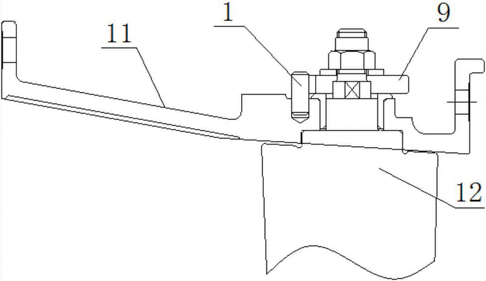
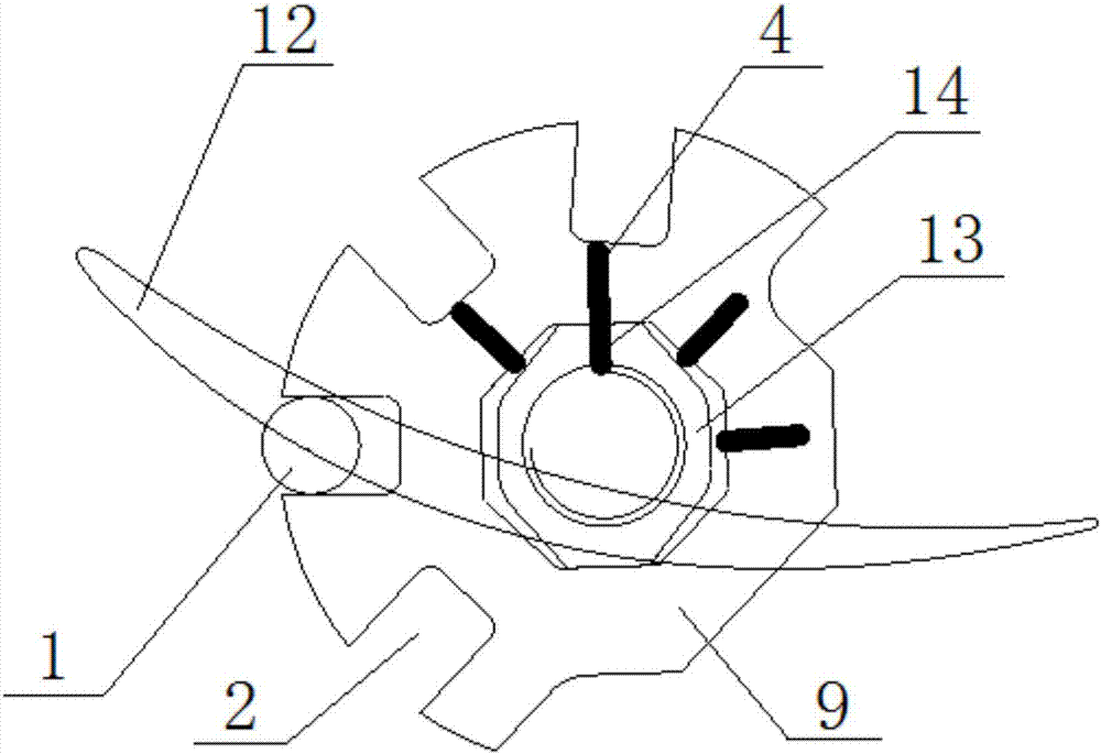
[0024] Such as image 3 As shown, when it is necessary to adjust the stator blade 12 from a certain angle to an angle a, the angle gauge block 9 is first picked up from the casing 11 and separated from the positioning pin 1 and the journal 13, the angle gauge block 9 is rotated and The octagonal through hole 3 is re-set on the journal 13, and at the same time, the journal mark 14 is aligned with the error-proof mark 4 of the angle a. At this time, the square groove 2 corresponding to the angle a cannot fall on the positioning pin 1. Rotate the angle gauge block 9 so that the square groove 2 can fall to the positioning pin 1. At this time, the journal 13 rotates synchronously under the action of the octagonal through hole 3, so the stator blades 12 also rotate synchronously, and the second rotation angle gauge block The angle of 9 is the adjustment angle, that is, the angle a; it should be noted that the adjustment angle is not the rotation angle, the adjustment angle is the fi...


PUM


Abstract

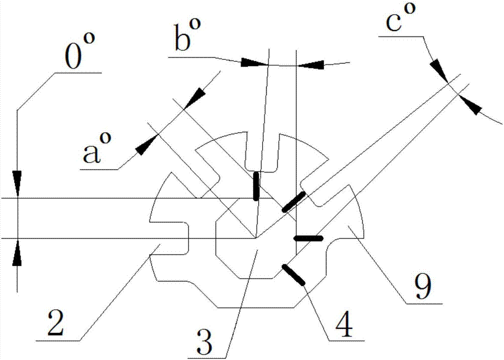
The invention provides a multi-angle angle gauge block. The multi-angle angle gauge block is used for adjusting the angle of a stator blade in a casing, a shaft neck is arranged on the stator blade, positioning pins are arranged on the casing, the angle gauge block is circular, N square grooves matched with the positioning pins are circumferentially arranged on the outer edge of the end face of the angle gauge block, the value range of N is larger than 1, the positions of N square grooves sequentially correspond to N adjusting angles of the stator blade, a polygon through hole is formed in the center of the angle gauge block, and is provided with M sides, M is equal to 2N, and the polygon through hole is in a regular polygon shape; the center lines perpendicular to the bottom faces of the square grooves pass through the center point of the polygon through hole, the center line of one square groove is further perpendicular to one set of opposite sides of the polygon through hole, and the included angle between the center line and the vertical line of the side, corresponding to the center line, of the polygon through hole is the adjusting angle.

Description

technical field [0001] The invention relates to the technical field of engine blade debugging, in particular to a multi-angle angle gauge block. Background technique [0002] In order to obtain better performance indicators for the fan of an aero-engine, the angle of the stator guide vane needs to be adjustable at the initial stage of design, but the angle adjustment of the existing technology is realized through a linkage ring, which uses a linkage ring through the rocker arm and the stator blade. Connected, and then the driver pushes the linkage ring to achieve the purpose of adjusting the entire stator blade at the same time. However, this technical solution has a large number of components, poor uniformity of the angles of each stator blade, and high cost, and the linkage ring adjustment mechanism is deformed during operation, so the angles of each stator blade are different, which will directly affect the performance of the fan. Contents of the invention [0003] In ...

Claims


Application Information

Patent Timeline
Patent Type & Authority Applications(China)
IPC IPC(8): F04D27/00F04D29/46F04D29/56
CPCF04D27/001F04D29/462F04D29/563F05D2260/83
Inventor 郑海亮王小颖胡丹
Owner AECC SHENYANG ENGINE RES INST
Learn More