
Built-in horizontal brace reinforced concrete shear wall

A reinforced concrete and shear wall technology, applied in the treatment of walls, building materials, construction, etc., can solve the problems of easy cracking of concrete, decreased seismic performance, difficult construction technology, etc., and achieve small prestress loss and energy consumption. The effect of improving, lightness of the floor structure system

Active Publication Date: 2017-07-07
GUANGXI UNIV
View PDF6 Cites 2 Cited by
  • Summary
  • Abstract
  • Description
  • Claims
  • Application Information

AI Technical Summary

Problems solved by technology

However, the height of the building continues to rise, and the traditional shear wall is difficult to meet the functional requirements of the building. The steel concrete shear wall has good bearing capacity and ductility, and has great development potential. However, in the process of earthquake, the steel concrete shear wall The concrete on the surface of the component is prone to cracks. During the earthquake, the cracks continue to develop and the damage is aggravated, which greatly reduces the seismic performance.
Prestressing can effectively limit the generation and development of cracks in concrete structures and improve the resilience performance of structures after unloading. Scholars at home and abroad have done a lot of research on prestressing, but the application of prestressing in the field of steel concrete shear walls still exists. Difficulties in structural form and construction technology

Method used


Image

  • Built-in horizontal brace reinforced concrete shear wall
  • Built-in horizontal brace reinforced concrete shear wall
  • Built-in horizontal brace reinforced concrete shear wall

Examples


Embodiment Construction

[0029] The present invention will be further described below in conjunction with the accompanying drawings and embodiments.

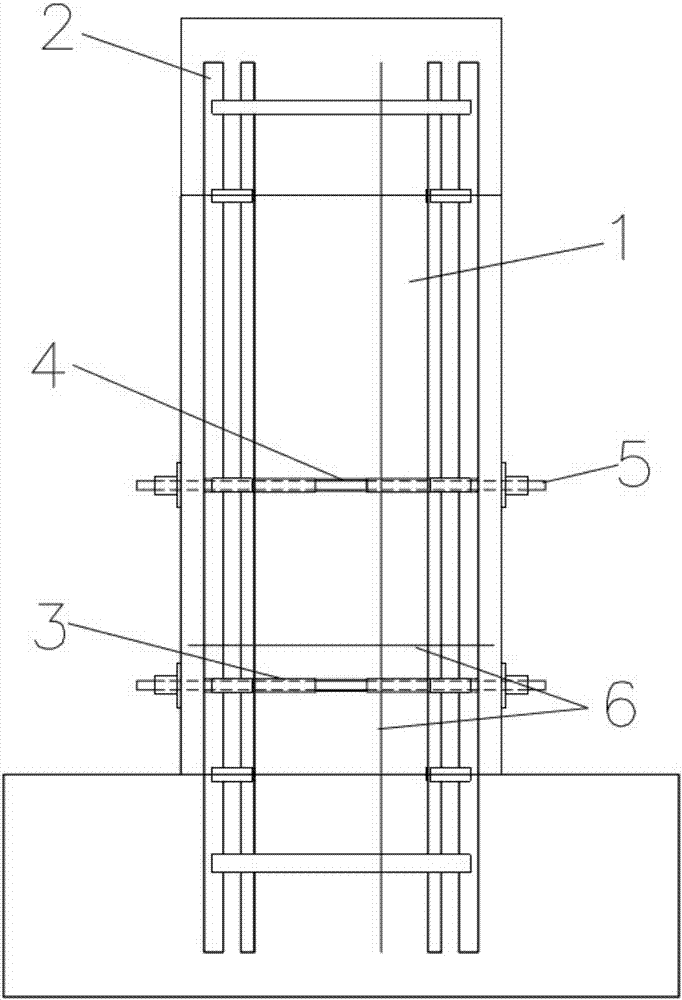
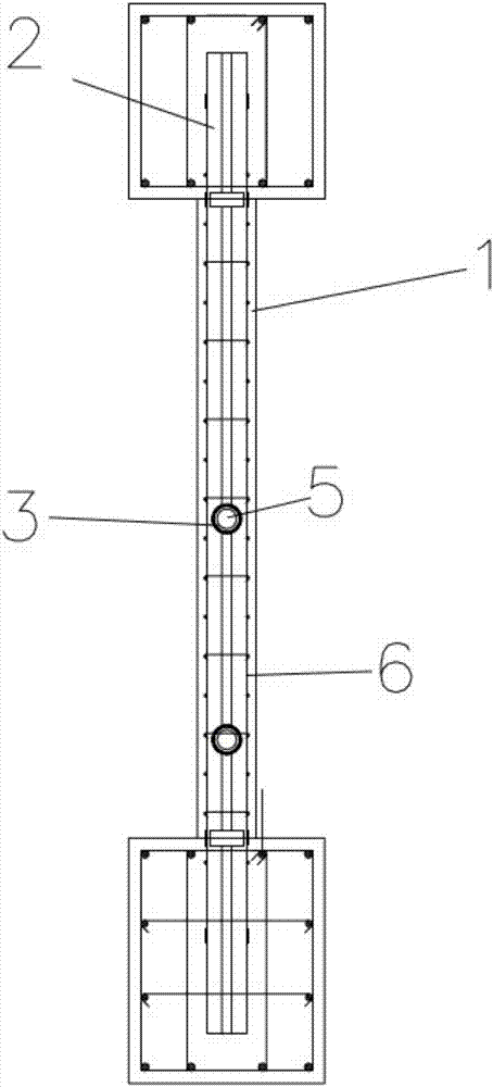
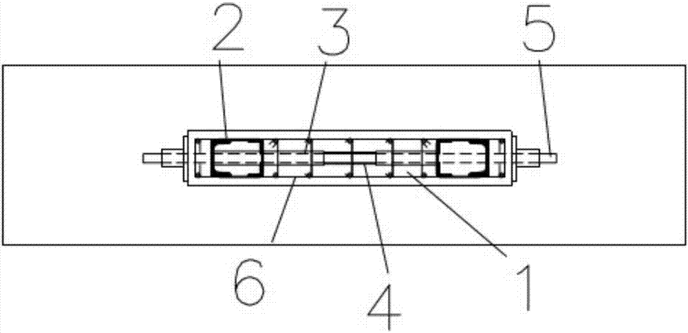
[0030] as attached Figure 1-3 As shown, the steel concrete shear wall of this embodiment includes a concrete wall support 1, a steel truss 2 built in the concrete wall support 1 and a prestressed horizontal diagonal brace. The prestressed horizontal diagonal brace includes a horizontal steel casing 3, a hose 4 and prestressed steel bars 5, wherein preferably, the hose 4 adopts a steel wire hose, and the prestressed steel bars 5 adopts precision-rolled rebar.

[0031] Such as Figure 4 As shown, it is a three-dimensional view of the built-in steel truss 2 in this embodiment, and the steel truss 2 is welded by channel steel, angle steel and flat steel.

[0032] Circular through holes are reserved at the corresponding positions on both sides of the steel truss 2 to form tunnels, and horizontal steel casings 3 are inserted into the two sides of the tunne...


PUM


Abstract

The invention relates to the technical field of concrete buildings, in particular to a built-in horizontal brace reinforced concrete shear wall. The built-in horizontal brace reinforced concrete shear wall comprises a concrete wall support, a steel truss arranged in the concrete wall support, and a prestressed horizontal brace. The built-in horizontal brace reinforced concrete shear wall is characterized in that the prestressed horizontal brace comprises horizontal steel casing pipes, hoses and prestressed steel bars; directly facing through holes are reserved in the two sides of the steel truss; the horizontal steel casing pipes penetrate into the through holes correspondingly; directly facing horizontal steel casing pipes communicate with each other through the hoses; the same prestressed steel bar penetrates into the interiors of the penetrating horizontal steel casing pipes and the hose; one end of each prestressed steel bar is anchored through a gasket nut; and after extending to the outside of the concrete wall support, the other end of each prestressed steel bar is applied with prestress and anchored through a gasket nut. The prestressing technology and the steel reinforced concrete composite structure technology are combined together, and the novel built-in horizontal brace reinforced concrete shear wall which limits crack development, improves the anti-seismic property of the shear wall component and is optimized in structure and easy to operate is provided.

Description

technical field [0001] The invention relates to the technical field of concrete buildings, in particular to a reinforced concrete shear wall with built-in horizontal braces. Background technique [0002] With the rapid development of my country's national economy and the continuous acceleration of urbanization, high-rise buildings are developing rapidly, and shear walls are the most basic vertical structural components in high-rise building structures. Lateral member. However, the height of the building continues to rise, and the traditional shear wall is difficult to meet the functional requirements of the building. The steel concrete shear wall has good bearing capacity and ductility, and has great development potential. However, in the process of earthquake, the steel concrete shear wall Concrete on the surface of components is prone to cracks. During the earthquake, the cracks continue to develop and the damage is aggravated, which greatly reduces the seismic performance...

Claims


Application Information

Patent Timeline
Patent Type & Authority Applications(China)
IPC IPC(8): E04B2/58E04G21/12
CPCE04B2/58E04G21/12
Inventor 钱凯邓小芳麦艺馨吴波王月明罗达滕晓丹贺盛
Owner GUANGXI UNIV
Learn More