Drain trap with backward flowing prevention function and difficult drying effect of water seal

A water trap and anti-backflow technology, applied in water supply installations, indoor sanitary pipe installations, buildings, etc., can solve the problems of loss of water seal, reduction of float floating stroke, backwater backflow, etc., to achieve effective sealing and maintain water sealing. Effect

Pending Publication Date: 2017-07-07
谢水清
View PDF2 Cites 1 Cited by
  • Summary
  • Abstract
  • Description
  • Claims
  • Application Information

AI Technical Summary

Problems solved by technology

[0004] ⑴No anti-drying effect: The water seal is an open structure. If the water appliances on the water trap are out of use for a period of time, the water trap will lose its water seal due to the reduction of water volatilization or even drying up, resulting in the inability to block, deodorize and prevent insects role (see Figure 7 );
[0005] (2) The water trap is easy to deposit dirt, which affects the drainage effect: the water storage structure of the water trap itself is easy to deposit dirt, and the kitchen waste in China is oily and easy to adhere to the pipe wall, and the thicker it is, the more viscous it is. It is also easy to adhere to debris, making the pipe shrink and smaller, which affects the drainage effect and becomes clogged. Therefore, the existing traps usually need to find professional workers to dredge and maintain them regularly;
[0006] ⑶ Does not have anti-return water performance: the existing trap structure does not have a one-way valve structure to prevent backwater and backflow. There will be the phenomenon of water backflow
[0009] ①Easy to block and slow water launch: easy to be leaked into the space under the float by mud and sand, difficult to discharge and silt in it, resulting in the reduction of the floating stroke of the float or even 0 over time
[0010] Since most houses will be decorated first and then put into use, it is unavoidable that a large amount of sediment will be discharged into the sewer through the water trap when cleaning the decoration site, which makes the above two patented water trap technologies unavoidable in the decoration. After finishing, the stroke of the float of the trap is significantly reduced, which makes it difficult for the trap to let larger food residues pass through, and it is easy to be blocked, and the water launching speed is always very slow
[0011] ② It is difficult for the float to keep floating up and down smoothly for a long time: because the float needs to be adapted to the cylindrical wall of the bottom cover in order to float up and down smoothly and to seal the lower port of the vertical waterway, the gap between the outer contour of the float and the cylindrical wall of the bottom cover is small. For example, when it is used in a kitchen basin, a large amount of oil stains are easily adsorbed on the surface of the parts of the trap, and the oil stains attached to the surface of the parts will become more and more viscous with time, which will affect the smooth floating of the float. If the weather is dry or If the water basin is stopped for a period of time, the float will also be solidified in the bottom cover due to the solidification of oil on the surface, which will cause the float to fail
[0012] ③ Closed water seal is prone to failure: the above two problems will cause the float to lose its effectiveness, and once the float fails, the lower seal of the closed water seal cannot be closed with the float, resulting in the inability to form a closed water seal and lose the long-term Maintain the effectiveness of the water seal

Method used


Image

  • Drain trap with backward flowing prevention function and difficult drying effect of water seal
  • Drain trap with backward flowing prevention function and difficult drying effect of water seal
  • Drain trap with backward flowing prevention function and difficult drying effect of water seal

Examples


Embodiment 1

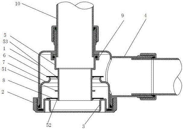
[0035] figure 1 The shown water trap is an embodiment of the present invention, including a water trap housing and a water sealing structure disposed in the housing, and the water trap housing includes a casing 1 and a bottom cover 2 . The shell 1 is cylindrical, with a drain pipe interface 4 on one side, external threads on the outer edge of the lower end, and a pipe joint connected to the sink drainer at the center of the top. The upper outer wall of the pipe joint has threads for the sink. Connector screw connection. The bottom cover 2 is provided with an internal thread adapted to the external thread of the shell 1 for connecting with the shell 1 to form a complete shell of the water trap. The bottom cover 2 has a vertically protruding protruding ring as the supporting protruding ring 3 , which is formed by the material of a local area of ​​the bottom cover 2 arching upward.

[0036] The water seal structure includes a water seal outer cover 7 , a water seal inner cover...

Embodiment 2

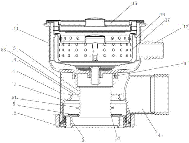
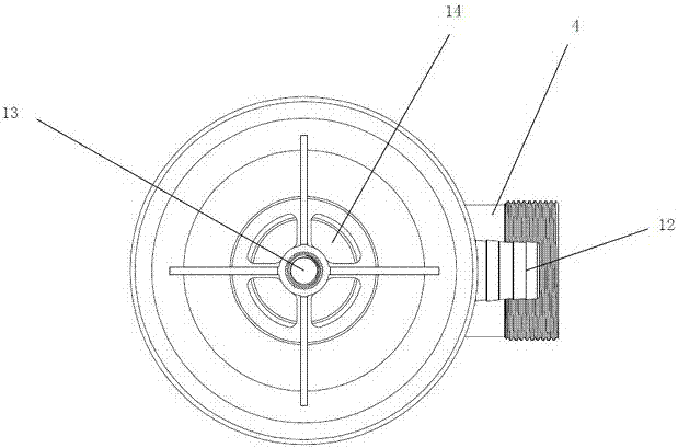
[0040] The difference from Embodiment 1 is: as figure 2 As shown, the sink drain is cup-shaped, which includes a cup-shaped drain main body 16 , a filter basket 17 and a surface cover 15 . Correspondingly, the top of the housing 1 in this embodiment is provided with a cylindrical body 11 whose inner diameter is larger than the outer diameter of the sink drainer, as a sleeve for fitting the drainer. A water overflow nozzle 12 is arranged on the sleeve, and when the water has no time to flow out through the water trap, the water is allowed to directly flow into the drainpipe from the water overflow nozzle 12 . Such as image 3 As shown, in this embodiment, a screw hole 13 is provided in the middle of the top surface of the water trap housing 1, and water leakage holes 14 are arranged around it. When installing, the drain main body 16 and the water trap housing 1 are connected at the screw holes 13 of the water trap housing 1 by screws and nuts, so that the water trap and the ...

Embodiment 3

[0042] The difference from Embodiment 1 is: as image 3 As shown, the water-sealed outer sleeve 7 is a vertical straight cylinder with an inner diameter larger than the water-sealed inner sleeve 5, and its bottom is sealed with the bottom cover 2, and the lower pipe section of the water-sealed inner sleeve 5 extends into the inner cavity of the water-sealed outer sleeve 7. At the position corresponding to the lower port of the vertical annular water channel, the inner wall of the water-seal outer cover 7 is provided with a radially protruding protruding ring along the inner perimeter, as a supporting protruding ring 71, which is connected with the water-sealing inner sleeve 5. The lower inner flange 52 is flush. In this embodiment, the outer diameter of the lower floating cover 8 is smaller than the inner diameter of the water-sealed overcoat 7, so that there is a distance between the outer contour edge of the lower floating cover 8 and the inner wall of the water-sealed overc...


PUM


Abstract

The invention discloses a water trap with anti-backflow and water seal that is not easy to dry up, comprising a water trap shell and a water seal structure, the water seal structure includes a water seal outer sleeve, a water seal inner sleeve, an upper floating cover and an upper floating cover, The bottom of the water seal inner sleeve is suspended above the bottom cover, the water seal outer sleeve is installed on the bottom cover, the water seal inner sleeve is inserted into the inner cavity of the water seal outer sleeve, and a vertical waterway and a water channel are formed between the water seal inner sleeve and the outer sleeve The upper port and the lower port, the upper floating cover and the lower floating cover are ring-shaped, which are set on the water seal inner sleeve and can be lifted and lowered along the outer wall of the water seal inner sleeve. port, between the water seal outer sleeve and the water seal inner sleeve and at the corresponding position of the lower port of the vertical water channel, the lower floating cover is built on the supporting structure to unidirectionally seal the lower port of the vertical water channel. A closed vertical water seal is formed between the outer jacket, the water-sealed inner sleeve, the upper floating cover and the lower floating cover, which can effectively prevent odor, cockroaches, backwashing and drying out.

Description

technical field [0001] The invention relates to a water trap, in particular to a water trap which can prevent backflow and has a water seal that is not easy to dry up. Background technique [0002] The water trap is a common drainage component used in the drainage system in the construction field. The existing water trap is used for deodorization and anti-exhaust gas in the drainage system of the water appliance. The earliest structure is the water trap of the S-shaped water container. The pipe forms a water-sealed structure, which is used to isolate the waste gas and odor in the drainage pipe from entering the room through the drainage pipe, and also prevents cockroaches from entering the room through the drainage pipe. [0003] Existing traps have structures such as S-type, P-type, sedimentary type, etc., to be suitable for different spaces (see Figure 6 ), however, these traps all have the following defects: [0004] ⑴No anti-drying effect: The water seal is an open str...

Claims


Application Information

Patent Timeline
Patent Type & Authority Applications(China)
IPC IPC(8): E03C1/28E03C1/288
CPCE03C1/28E03C1/288
Inventor 谢水清
Owner 谢水清
Why Eureka
Try Eureka