Eureka AIR delivers breakthrough ideas for toughest innovation challenges, trusted by R&D personnel around the world.

Gas flow guiding device

An air-guided and leading technology, applied in road cleaning, construction, cleaning methods, etc., can solve the problems of poor applicability, limited effect, and dangerous driving in rainy days, and achieve the effect of improving traffic safety.

Inactive Publication Date: 2017-07-07
SOUTHWEST JIAOTONG UNIV
View PDF7 Cites 2 Cited by
  • Summary
  • Abstract
  • Description
  • Claims
  • Application Information

AI Technical Summary

Problems solved by technology

Due to the lubricating effect of the water film, the driving car is prone to deviate from the normal driving direction and hydroplaning occurs. In severe cases, accidents such as sideslip and rear-end collision may even occur.
At the same time, it also affects the driving of vehicles behind, causing driving hazards
Traditionally, road engineering measures are usually used to prevent the occurrence of road water accumulation by improving the road surface alignment conditions. However, over the years, practical experience at home and abroad has proved that only relying on road infrastructure and traditional management methods to solve road water accumulation The problem is that not only the construction period is long, the cost is high, it consumes a lot of manpower and material resources, the environmental pollution is serious, and its effect of preventing road accumulation is very limited
Most of the traditional anti-skid devices are anti-skid through the traditional way of installing anti-skid chains (for example, the patent number is CN205970662U, a modular automobile anti-skid chain that is easy to disassemble), and it is inconvenient to disassemble and assemble, and the applicability in rainy days is not good

Method used


Image

  • Gas flow guiding device
  • Gas flow guiding device
  • Gas flow guiding device

Examples


Embodiment Construction

[0023] The present invention will be further described below by accompanying drawing:

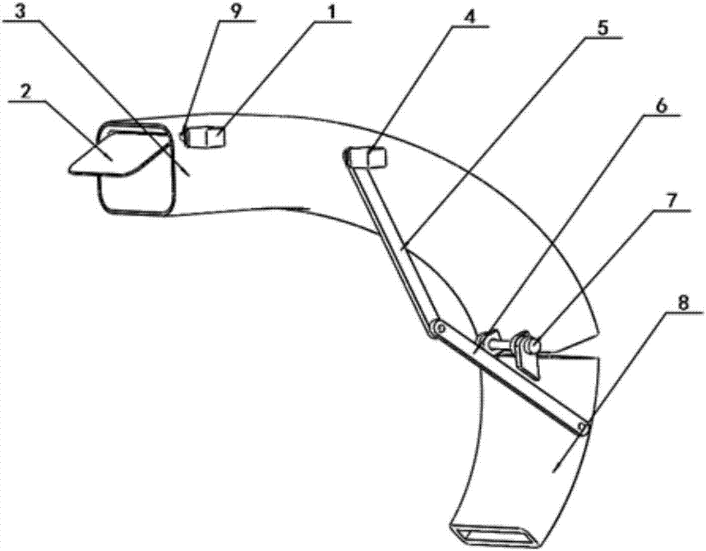
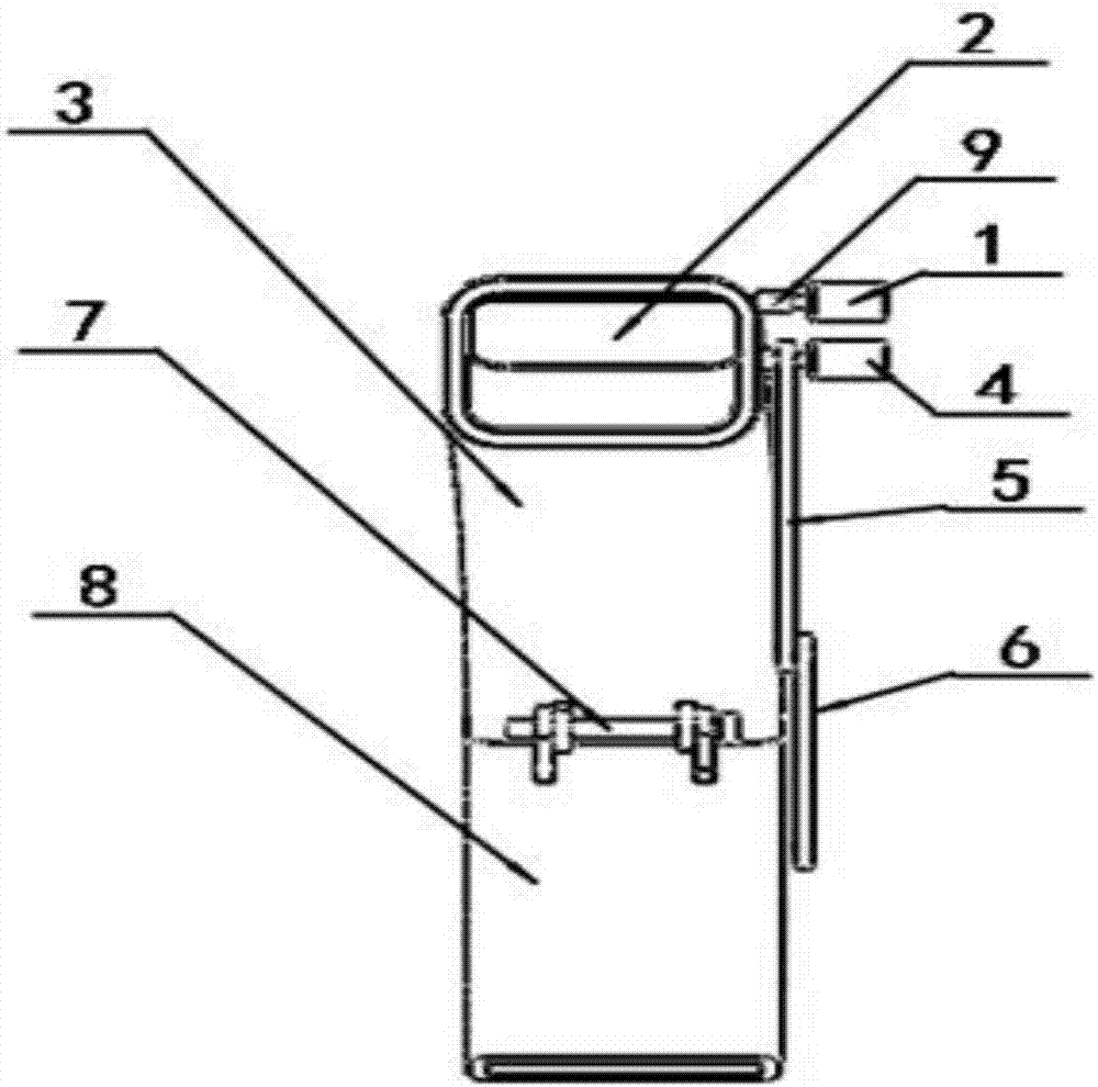
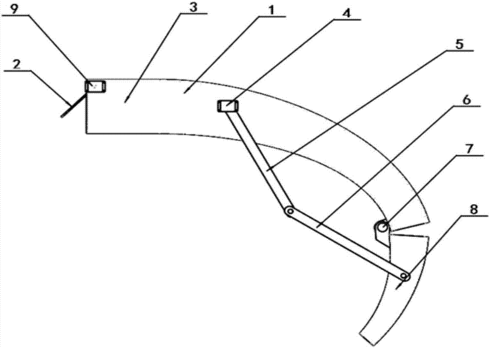
[0024] An airflow guiding device, comprising a front air guide pipe 3 and a rear air guide pipe 8, the air inlet baffle 2 is located at the front end of the front air guide pipe 3, the cross section of the front air guide pipe 3 is a structure with a large front and a small rear, and the side of the front air guide pipe 3 is provided with Motor one 1, its shaft is connected with the rotating shaft of air inlet baffle 2 by shaft coupling 9, the middle part side of front air duct 3 is provided with motor two 4, and its output shaft is fixed with an end of connecting rod one 5, and connecting rod one 5 The other end of the connecting rod 2 is hinged with one end of the connecting rod 26, the other end of the connecting rod 26 is hinged with the front end of the rear air guide pipe 8, the front air guide pipe 3 and the rear air guide pipe 8 are hinged through the pin 7, and the front end cross s...


PUM


Abstract

The invention provides a gas flow guiding device, and relates to the technical field of car safety. The gas flow guiding device comprises a front guide duct and a rear guide duct, an air inlet baffle is located at the front end of the front guide duct, the cross section of the front guide duct is of a front-big and rear-small structure, a first motor is arranged on the side face of the front guide duct, a shaft of the front guide duct is connected with a rotating shaft of the air inlet baffle through a coupling, a second motor is arranged on the middle side face of the front guide duct, an output shaft of the front guide duct is fixed to one end of a first connecting rod, the other end of the first connecting rod is hinged to one end of a second connecting rod, the other end of the second connecting rod is hinged to the front end of the rear guide duct, the front guide duct and the rear guide duct are hinged through a pin roll, and the cross section of the front end of the rear guide duct is the same as the cross section of the tail end of the front guide duct. A seam allowance is formed in the position of a juncture of the tail end of the front guide duct and the front end of the rear guide duct. The gas flow guiding device is used for car wading skid resistance.

Description

technical field [0001] The invention relates to the technical field of automobile safety. Background technique [0002] The rainwater that falls on the road surface during the rainy season moves along the direction of the synthetic slope, forming a water film on the road surface. Due to the lubricating effect of the water film, the driving car is prone to deviate from the normal driving direction and hydroplaning occurs. In severe cases, accidents such as side skidding and rear-end collisions may even occur. Simultaneously, it also affects the driving of vehicles behind, causing driving danger. Traditionally, road engineering measures are usually used to prevent the occurrence of road water accumulation by improving the road surface alignment conditions. However, over the years, practical experience at home and abroad has proved that only relying on road infrastructure and traditional management methods to solve road water accumulation The problem is that not only the cons...

Claims


Application Information

Patent Timeline
Patent Type & Authority Applications(China)
IPC IPC(8): E01H1/10
CPCE01H1/108
Inventor 张祖涛张兴田杜静霜钱佳莹卢锋柳泽晨王一铭王铖刘紫桐
Owner SOUTHWEST JIAOTONG UNIV
Why Eureka
Eureka Blog
Learn More