
Battery core and jig separation mechanism

A technology for separating mechanisms and batteries, which is applied in the direction of assembling batteries, circuits, electrical components, etc.

Active Publication Date: 2017-06-30
HUIZHOU JINYUAN PRECISION AUTOMATION EQUIP
View PDF3 Cites 2 Cited by
  • Summary
  • Abstract
  • Description
  • Claims
  • Application Information

AI Technical Summary

Problems solved by technology

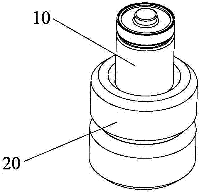
[0004] During the design process, there will be such a technical problem. Before the assembly line drives the jig 20 equipped with the cylindrical battery cell 10 to the pressing device, the cylindrical battery cell 10 needs to be taken out of the jig 20

Method used


Image

  • Battery core and jig separation mechanism
  • Battery core and jig separation mechanism
  • Battery core and jig separation mechanism

Examples


Embodiment Construction

[0027] In order to facilitate the understanding of the present invention, the present invention will be described more fully below with reference to the associated drawings. Preferred embodiments of the invention are shown in the accompanying drawings. However, the present invention can be embodied in many different forms and is not limited to the embodiments described herein. On the contrary, the purpose of providing these embodiments is to make the disclosure of the present invention more thorough and comprehensive.

[0028] It should be noted that when an element is referred to as being “fixed” to another element, it can be directly on the other element or there can also be an intervening element. When an element is referred to as being "connected to" another element, it can be directly connected to the other element or intervening elements may also be present. The terms "vertical," "horizontal," "left," "right," and similar expressions are used herein for purposes of ill...


PUM


Abstract

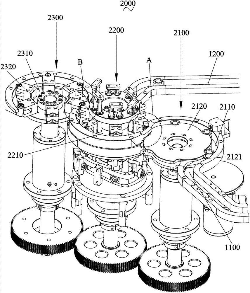
The invention discloses a battery core and jig separation mechanism which comprises a first material rotating device, a second material rotating device and a third material rotating device, wherein the first material rotating device is provided with an arc-shaped material rotating channel; the second material rotating device is provided with a circular material rotating channel; the first material rotating device comprises a battery core jig loading turntable; a battery core and jig cutting groove is formed in the edge of the battery core jig loading turntable; the second material rotating device comprises a battery core and jig separation cam, a battery core and jig separation turntable, a battery core ejection rod and a battery core fixing block; the third material rotating device comprises a battery core loading turntable and a battery core clamping block; the battery core clamping block is fixedly mounted at the edge of the battery core loading turntable; the structure of the battery core clamping block is identical with that of the battery core fixing block; the battery core fixing block and the battery core clamping block are respectively rotated through the battery core and jig separation cam and the battery core loading turntable to form tangent fit. The battery core and jig separation mechanism disclosed by the invention can automatically take a cylindrical battery core out of a jig to make a preparation for pressing of the battery core in the next working procedure.

Description

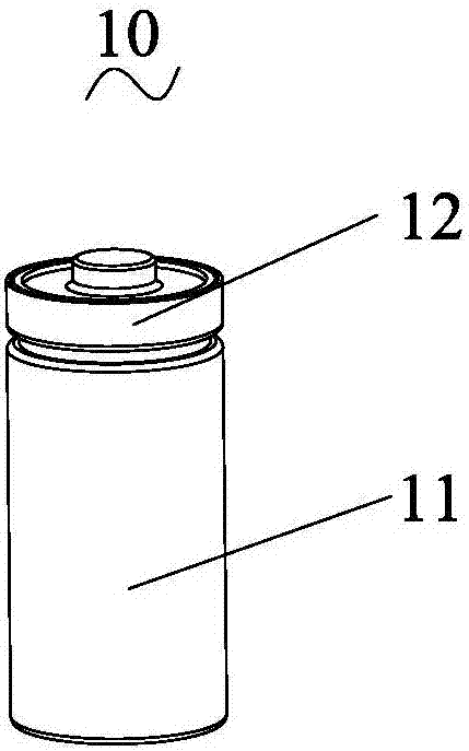
technical field [0001] The invention relates to the field of battery mechanical automation production, in particular to a battery cell jig separation mechanism. Background technique [0002] With the continuous development of society and the continuous advancement of science and technology, mechanical automation production has become a development trend, and gradually replaces traditional manual labor, injecting new power sources for the sustainable development of enterprises. Therefore, battery manufacturing enterprises also need to keep pace with the times, actively promote technological transformation through transformation and upgrading, and vigorously develop mechanical automation production, so as to improve the level of "smart manufacturing" of enterprises and achieve sustainable development of enterprises. [0003] Such as figure 1 As shown, it is a structural diagram of a cylindrical cell 10. The cylindrical cell 10 includes a cell body 11 and a top cover 12 connec...

Claims


Application Information

Patent Timeline
Patent Type & Authority Applications(China)
IPC IPC(8): H01M10/04H01M6/00
CPCH01M6/005H01M10/0404H01M10/0422Y02E60/10Y02P70/50
Inventor 李养德李斌王世峰刘金成陈正国
Owner HUIZHOU JINYUAN PRECISION AUTOMATION EQUIP
Learn More