
Power transmission line distributed ice-melting monitoring method

A transmission line, distributed technology, applied in the direction of measuring devices, measuring heat, instruments, etc., can solve the problems of not being able to understand the icing state in real time, wire galloping, mechanical and electrical performance degradation, etc., to facilitate automatic analysis and judgment, intelligent high degree of effect

Inactive Publication Date: 2017-06-30
ELECTRIC POWER SCI RES INST OF GUIZHOU POWER GRID CO LTD
View PDF4 Cites 0 Cited by
  • Summary
  • Abstract
  • Description
  • Claims
  • Application Information

AI Technical Summary

Problems solved by technology

[0002] Ice and snow accumulation on high-voltage transmission lines will lead to a sharp decline in its mechanical and electrical performance, causing major electrical accidents such as wire galloping, tower tilting or even tower collapse, wire breakage, and insulator flashover, which seriously affect the safe operation of the power system
At this time, it is very important to monitor the icing status of the transmission line in real time. However, the traditional methods are based on point-based monitoring, and it is impossible to know the icing status of tens of kilometers along the entire line in real time. Moreover, when the icing is serious, the ice melting technology has become a research boom At present, the mainstream ice melting technology is still DC ice melting. Although it is convenient and fast, it absolutely avoids multiple accidents under the influence of ice, but the loss caused by power outages is not to be underestimated. Therefore, real-time and accurate ice melting signals are known to It is very critical to judge whether the emergency mechanism is activated or not; in addition, in the case of large-scale deicing or deicing in different periods, there will be risk accidents of line breakage and tower collapse. implementation will be difficult

Method used


Image

  • Power transmission line distributed ice-melting monitoring method
  • Power transmission line distributed ice-melting monitoring method
  • Power transmission line distributed ice-melting monitoring method

Examples


Embodiment Construction

[0016] The present invention will be described in further detail below in conjunction with the accompanying drawings and examples, but the examples should not be construed as limiting the present invention.

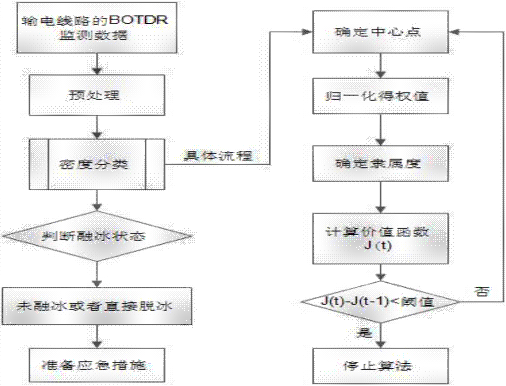
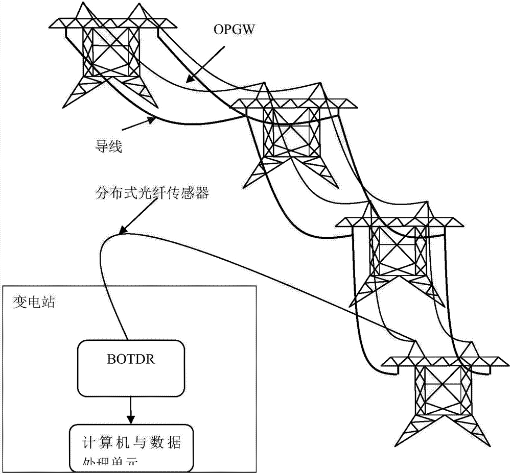
[0017] see Figure 1 to Figure 2 , the distributed ice-melting monitoring method of the transmission line of the present invention comprises the following steps:

[0018] Step 1. Use the Brillouin Optical Time Domain Reflectometer to monitor the monitoring data F(x i ,t m );

[0019] Step 2: Analyze and process according to the monitoring signal, and extract the pre-processed signal data F in real time m (x i ,t m );

[0020] Step 3. Set the initial center P of the data set i , for density classification;

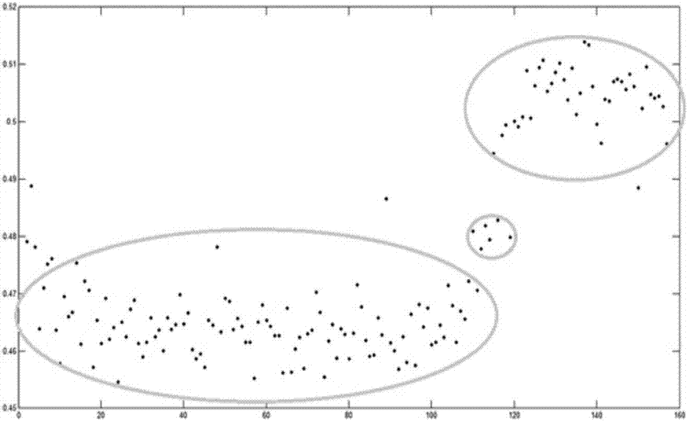
[0021] Step 4. Classify the results according to the density {R 1 , R 2}, to distinguish the meaning of the signal representation at this time;

[0022] Step 5: Eliminate abnormal points or isolated points, and determine whether the ice melting or deicing is...


PUM


Abstract

The invention discloses a power transmission line distributed ice-melting monitoring method. The method comprises the following steps that: step 1, a Brillouin optical time domain reflectometer is adopted to monitor signal data obtained by a power transmission line (OPGW); step 2, analysis processing is performed according to monitoring signals, and pre-processed signal data are extracted in real time; step 3, the initial center of a data set is set, and density classification is performed; step 4, meanings characterized by the signals are distinguished according to the result of the density classification; and step 5, abnormal points or isolated points are excluded, and whether ice-melting or ice stripping is terminated at this moment is judged, and therefore, the distributed ice-melting monitoring of the power transmission line is realized. The power transmission line distributed ice-melting monitoring method of the invention has the advantages of high intelligence degree, high real-time response capability and high accuracy of recognition results. The power transmission line distributed ice-melting monitoring method can facilitate a computer to automatically analyze and judge the distributed ice-melting information features of the power transmission line and can be widely applied to the power transmission line to perform real-time melting ice monitoring.

Description

technical field [0001] The invention relates to the monitoring of icing on transmission lines, in particular to a monitoring method for distributed ice melting of transmission lines. Background technique [0002] Ice and snow accumulation on high-voltage transmission lines will lead to a sharp decline in its mechanical and electrical performance, causing major electrical accidents such as conductor galloping, tower tilting or even tower collapse, disconnection, and insulator flashover, which seriously affect the safe operation of the power system. At this time, it is very important to monitor the icing status of the transmission line in real time. However, the traditional methods are based on point-based monitoring, and it is impossible to understand the icing status of tens of kilometers along the entire line in real time; and when the icing is serious, the ice melting technology has become a research boom At present, the mainstream ice melting technology is still DC ice me...

Claims


Application Information

Patent Timeline
Patent Type & Authority Applications(China)
IPC IPC(8): G01B11/16G01K11/32G01K11/322
CPCG01B11/18G01K11/32G01K11/322
Inventor 黄良吕黔苏庄红军魏延勋卢金科王琨高正浩王颖陈勇宇张强永李克明陈沛龙陆岫昶
Owner ELECTRIC POWER SCI RES INST OF GUIZHOU POWER GRID CO LTD
Learn More