Building outline forming machine

A technology for building outlines and forming machines, which is used in construction, building construction, and processing of building materials, etc., can solve problems such as work quality and efficiency limitations, low equipment integration, and long assembly cycle, so as to avoid clogging of feeding materials. The effect of reducing the use of land and improving the quality of work

Active Publication Date: 2017-06-30
BUILDERA CONSTR TECH SHANGHAI CO LTD
View PDF16 Cites 3 Cited by
  • Summary
  • Abstract
  • Description
  • Claims
  • Application Information

AI Technical Summary

Problems solved by technology

[0002] The existing building contour forming machine not only has a complex structure, but also has a long assembly cycle, and occupies a large area. It is easily affected by site factors during installation, and the quality and efficiency of the operation are limited. Moreover, the existing equipment is relatively integrated. Low, some processes still need to be manually operated, such as painting the wall, the existing technology is still mainly manual, only part of the mechanized construction is used, and there are relatively large restrictions in terms of material delivery and movement of the end spray gun. , and the work efficiency is relatively low

Method used


Image

  • Building outline forming machine
  • Building outline forming machine
  • Building outline forming machine

Examples


Embodiment 1

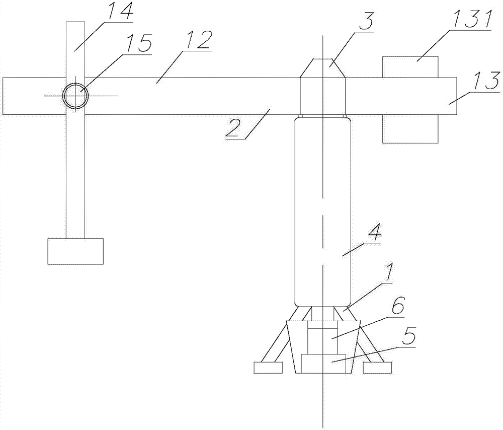
[0034] The silo 4 includes a plurality of sub-silos for storing raw materials of different types or particle sizes. A stirring mechanism 6 and a conveying mechanism 5 are arranged at the bottom of the silo 4. The conveying mechanism 5 is connected to the discharge port of the stirring mechanism 6. Each sub-silo can store raw materials such as sand and cement, and additives such as wet agent, quick-drying agent, and thickener according to the design requirements. The stirring mechanism 6 sends the raw materials to the material output unit 100 through the conveying mechanism 5 after stirring. Preferably, an electromagnetic switch is provided at the outlet of the sub-bins, and the control unit controls the electromagnetic switches to add the raw materials in each sub-bin to the stirring mechanism 6 in proportion, and then send them to the conveying mechanism 5 after mixing.

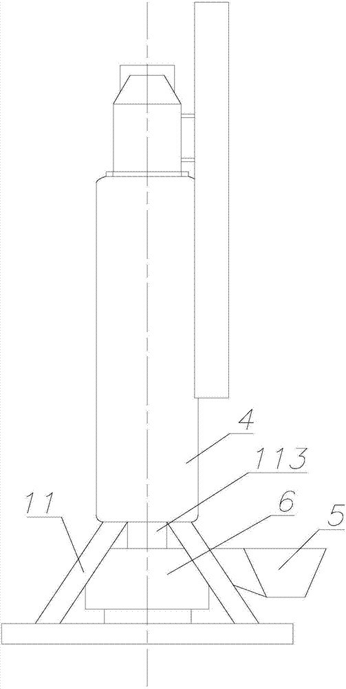
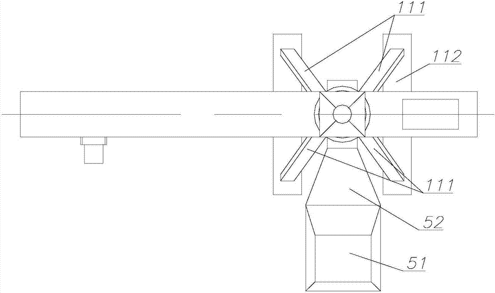
[0035] like figure 2As shown, the stirring mechanism 6 is arranged in the bottom frame 11 of the base 1 ...

Embodiment 2

[0039] like Figure 4 As shown, the base 1 is provided with a pneumatic conveyor 500 that cooperates with the silo 4, and a stirring mechanism 6 is arranged above the silo 4. The silo 4 is used to store dry materials such as dry powder mortar. The raw materials are transported to the stirring mechanism 6 to stir the dry powder mortar, and then the stirred dry powder mortar is sent to the material output unit 100 .

[0040] The powder is transported by the pneumatic conveyor 500, and the dry powder mortar is pneumatically conveyed, which can effectively reduce the difficulty of feeding and avoid clogging of the feeding pipe, especially for operations on high floors. Mechanism 6, the powder is stirred by the stirring mechanism 6 and then fed to the material output unit 100 horizontally along the rotary platform, so that the stirred material is not easy to block the pipe, and the feeding is more stable, improving the working quality. Of course, the pneumatic conveyor 500 can als...


PUM


Abstract

A building outline forming machine comprises a rotating platform and a base used for supporting the rotating platform. The rotating platform is mounted on the base through a rotary table and comprises a swing arm and a balance arm which are connected and separately arranged on the two sides of the rotary table. The balance arm is provided with a counterweight unit. The swing arm is provided with a cantilever which is connected with the swing arm through a mobile mechanism. The mobile mechanism drives the cantilever to horizontally move on the swing arm. The cantilever is provided with a 3D printing module. The rotating platform and the 3D printing module are supported aloft for operation through the base and the ground, the occupied using area of the whole machine can be effectively decreased, mounting of the building outline forming machine at a construction site is not limited by site factors, and the 3D printing module is driven to rotate around the base through the rotating platform so that a large operation range can be covered while the size of the whole machine is decreased, and the mounting position of the outline forming machine can be flexibly selected.

Description

technical field [0001] The invention relates to the field of construction equipment, in particular to a building contour forming machine. Background technique [0002] The existing building contour forming machine not only has a complex structure, but also has a long assembly cycle, and occupies a large area. It is easily affected by site factors during installation, and the quality and efficiency of the operation are limited. Moreover, the existing equipment is relatively integrated. Low, some processes still need to be manually operated, such as painting the wall, the existing technology is still mainly manual, only part of the mechanized construction is used, and there are relatively large restrictions in terms of material delivery and movement of the end spray gun. , and the operating efficiency is relatively low. Contents of the invention [0003] The purpose of the present invention is to overcome the defects of the prior art and provide a building contour forming m...

Claims


Application Information

Patent Timeline
Patent Type & Authority Applications(China)
IPC IPC(8): E04G21/00
CPCE04G21/00
Inventor 蒋旭峰
Owner BUILDERA CONSTR TECH SHANGHAI CO LTD
Why Eureka
Try Eureka