
Anchor rod bracing wire foundation applicable to rock base and construction method thereof

A rock foundation and bolt technology, which is applied in the construction field of the bolt and cable foundation, can solve the problems of foundation safety hazards, poor cable stability, and loose connection, etc., and achieves the elimination of safety hazards, strong pull-out resistance, and not easy to suffer. pull cracking effect

Inactive Publication Date: 2017-06-30
河南和德新能源有限公司
View PDF5 Cites 2 Cited by
  • Summary
  • Abstract
  • Description
  • Claims
  • Application Information

AI Technical Summary

Problems solved by technology

Its shortcomings are: 1. The construction of the cable reel needs to excavate the foundation and backfill, which will damage the surface environment; in projects that need to use a large number of guy wires, large-scale intensive excavation of the foundation pit will cause the foundation to loosen, unable to fix the guy wires, and even affect the overall environment. The stability of the project; 2. Excavating foundation pits on rock foundations is difficult, costly, and inefficient; 3. If blasting is used to excavate rock foundations, the stability of the foundation will be seriously damaged, which will bring potential safety hazards to the foundation and damage the foundation. The ecological environment of the site, and did not take advantage of the solid bearing capacity of the rock foundation itself
[0003] Chinese patent CN104594375A discloses a new type of bolt and cable foundation, but the disclosed technical solution does not consider the volume shrinkage of ordinary concrete grouting material after hardening. Gaps, poor combination, poor stability of the pull wire

Method used


Image

  • Anchor rod bracing wire foundation applicable to rock base and construction method thereof

Examples


Embodiment Construction

[0026] The embodiments of the present invention will be described in detail below in conjunction with the accompanying drawings. This embodiment is implemented on the premise of the technical solution of the present invention, and detailed implementation methods and specific operating procedures are provided, but the scope of protection of the present invention is not limited to the following Described embodiment.

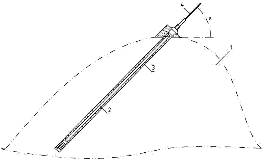
[0027] Such as figure 1 As shown, the bolt and stay wire foundation suitable for rock foundations according to the present invention is composed of a rock hole set on a rock foundation 1, an expanding shell type prestressed hollow grouting bolt 2, a bolt grouting material 3 and a stay wire 4. The angle a formed by backguy 4, expansion shell type prestressed hollow grouting anchor rod 2 and rock hole and horizontal plane is consistent; The other end of the stress hollow grouting anchor 2 is inserted into the rock hole, and the gap between the expansion shell type p...


PUM


Abstract

The invention discloses an anchor rod and cable foundation suitable for rock foundations, which is composed of rock holes, anchor rods, anchor rod grouting materials and guy wires set on the rock foundation; the guy wires, anchor rods, rock holes and horizontal planes The angles are consistent; one end of the anchor rod is connected with the stay wire, the other end of the anchor rod is inserted into the rock hole, and the gap between the anchor rod and the rock hole is filled with anchor rod grouting material. The invention has the advantages that the stability of the original rock structure is fully utilized, the strength of the anchor rod stay wire base structure is high, the pullout resistance of the stay wire is strong, and the anchor pull force of more than 20 tons can be achieved, which meets the practical application requirements. The prestressed construction method is used to obtain prestressed pressure on the grouting material. The prestressed pressure on the grouting material can reduce or offset the tensile stress caused by the external load (that is, the pull wire), making the hardened grouting material less susceptible to tensile cracking , the tensile performance is better, the pulling resistance of the cable is stronger, and the overall structure of the anchor cable is more stable.

Description

technical field [0001] The invention relates to an anchor rod stay wire foundation suitable for rock foundations, and also relates to a construction method of the anchor rod stay wire foundation. Background technique [0002] The guy wires are set up for stabilizing the poles, towers, and viaducts. Through the guy wires, they can balance the force of the beams, towers, and viaducts, resist the wind pressure, and prevent the towers from bending and toppling. The traditional guy wire fixed foundation construction requires excavation of guy wire pits, Lower the cable reel, fill the soil layer by layer and compact it, and finally fix the upper end of the cable on the tower. Its shortcomings are: 1. The construction of the cable reel needs to excavate the foundation and backfill, which will damage the surface environment; in projects that need to use a large number of guy wires, large-scale intensive excavation of the foundation pit will cause the foundation to loosen, unable to ...

Claims


Application Information

Patent Timeline
Patent Type & Authority Applications(China)
IPC IPC(8): E02D5/74
CPCE02D5/74
Inventor 杨大楼高学存邵明山
Owner 河南和德新能源有限公司
Learn More