a vibrator

A vibration exciter and excitation technology, applied in the direction of vibrating fluid, metal processing equipment, measuring/indicating equipment, etc., can solve the problems of low bad excitation, difficulty in controlling the uniformity of excitation, and uncontrollable movement, etc., to achieve Excellent time-domain and frequency-domain characteristics of excitation force, improved quality and repeatability of excitation, and precise controllable excitation time

Inactive Publication Date: 2020-04-21
SHENZHEN GRADUATE SCHOOL TSINGHUA UNIV
View PDF6 Cites 0 Cited by
  • Summary
  • Abstract
  • Description
  • Claims
  • Application Information

AI Technical Summary

Problems solved by technology

Among them, manual excitation has many disadvantages: First, the quality control of excitation is difficult, even for skilled operators, the proportion of bad excitation is not low
Second, the uniformity of each excitation is also difficult to control, and the method of single-point multiple excitation and averaging is difficult to achieve the purpose of improving accuracy.
Third, for the machine tool spindle system, the modal parameters under its operation have more application value for dynamic performance analysis, but the method of manual excitation cannot be used when the spindle is rotating
Furthermore, the existing mechanical vibrators no longer control the movement of the vibrating part after the acceleration of the vibrating part is completed, that is, the motion of the actual vibrating time period cannot be controlled.
Therefore, the existing methods all have the disadvantage that neither the excitation time nor the excitation displacement can be accurately controlled.

Method used


Image

  • a vibrator
  • a vibrator
  • a vibrator

Examples


Embodiment Construction

[0029] The present invention will be further described below with reference to the accompanying drawings and in combination with preferred embodiments.

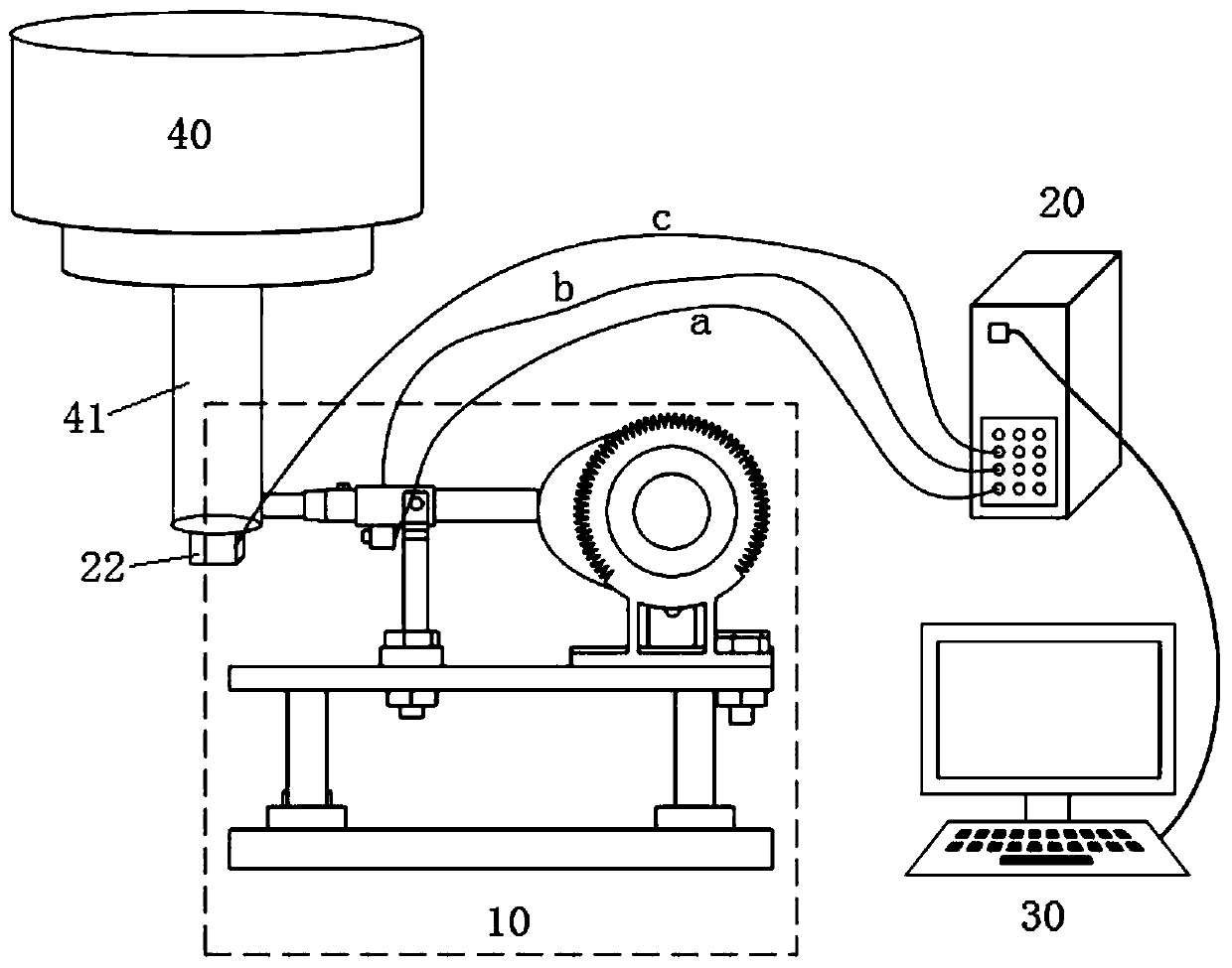
[0030] Such as figure 1 As shown, the novel vibrator of the preferred embodiment of the present invention is applied to the machine tool spindle system 40 (that is, in this embodiment, the body to be excited is the main shaft 41 in the machine tool spindle system 40), including: the vibration excitation device 10 , the sensing and measuring device 20 and the analysis terminal device 30, wherein the exciting device 10 is used to realize precise and controllable exciting motion, and the sensing and measuring device 20 is used to measure the exciting force, the exciting response and the exciting displacement, The analysis terminal device 30 is used to analyze and calculate the measurement data, and obtain the modal parameters of the main shaft 41, such as modal frequency, modal mass, modal stiffness, damping ratio, and the like....


PUM


Abstract

The invention discloses a novel vibration exciter. The novel vibration exciter comprises a vibration excitation device. The vibration excitation device comprises a driving mechanism, a transmission mechanism, a cam mechanism and a driven mechanism, wherein the driving mechanism is connected with the cam mechanism through the transmission mechanism to drive the cam mechanism to rotate, the driven mechanism is arranged between the cam mechanism and a to-be-excited body so that the cam mechanism can rotate to drive the driven mechanism to make contact with and impact the to-be-excited body, and thus, vibration excitation can be conducted on the to-be-excited body. The novel vibration exciter provided by the invention can precisely control the vibration excitation time and the vibration excitation displacement, and is especially suitable for a machine tool spindle system.

Description

technical field [0001] The invention relates to the field of modal analysis, in particular to a novel vibrator. Background technique [0002] Modal analysis is a modern method to study the dynamic characteristics of structures, and it is the application of system identification method in the field of engineering vibration. Mode is the natural vibration characteristic of mechanical structure, each mode has specific natural frequency, damping ratio and mode shape; these mode parameters can be obtained by calculation or test analysis, such a calculation or test analysis process is called mode state analysis. The modal parameters are obtained by identifying the collected system input and output signals through experiments, which is called experimental modal analysis. [0003] Vibrational modes are an inherent, integral property of elastic structures. By obtaining the modal parameters of the structure through the modal analysis method, the actual vibration response of the stru...

Claims


Application Information

Patent Timeline
Patent Type & Authority Patents(China)
IPC IPC(8): B06B1/16B23Q17/00B23Q17/12
CPCB06B1/161B23Q17/00B23Q17/12
Inventor 许超冯平法叶健黄双刚
Owner SHENZHEN GRADUATE SCHOOL TSINGHUA UNIV
Why Eureka
Try Eureka