Trolley for adjusting temperature and humidity of chicken house
A technology of humidity regulation and chicken house temperature, which is applied in poultry cages or houses, application, poultry industry, etc., can solve the problems of increasing the production cost of chicken farms, not being able to play a role, and consuming large power, so as to achieve convenient cooling and humidification and Disinfection and sterilization, easy to purchase, and low equipment cost
- Summary
- Abstract
- Description
- Claims
- Application Information
AI Technical Summary
Problems solved by technology
Method used
Image
Examples
Embodiment 1
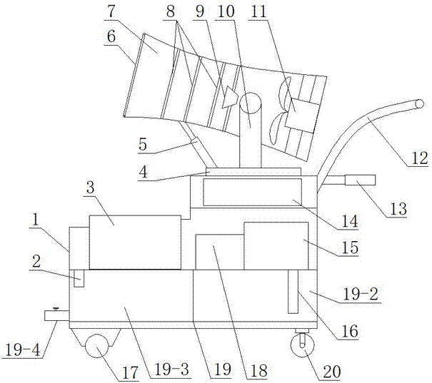
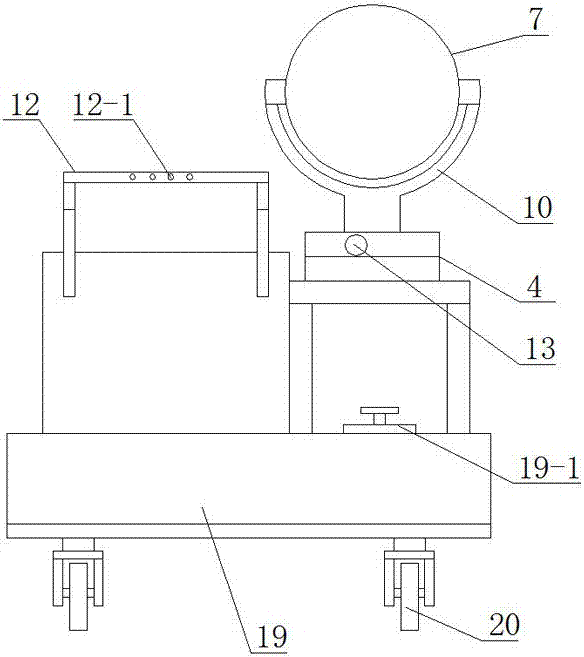
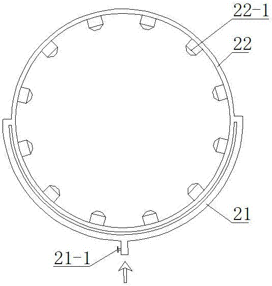
[0035] see figure 1 , figure 2 : a trolley for regulating temperature and humidity in a henhouse, comprising a movable frame body 1, the bottom of the frame body 1 is equipped with an active traveling wheel 17 and a driven traveling wheel 20, the active traveling wheel 17 is driven by a traveling motor to walk, and the slave The moving walking wheel 20 is a universal wheel, relying on the operator to control the hand lever 12 arranged on one side of the frame body 1 as required to adjust the direction of the temperature and humidity adjustment trolley in the henhouse, so as to realize the movement of the dolly in the henhouse. The lower part of the frame body 1 is provided with a water tank 19, and the upper part of the frame body 1 is provided with a generator 3, a water pump 15, a pipeline booster pump 18 and an air cylinder, and the air cylinder includes one or more cylindrical bodies 7, each The front end of the cylinder is provided with a spray mechanism 6, the rear end...
Embodiment 2
[0047] see figure 1 , 2 , 5, 6, further as a preferred solution, the air cylinder is arranged on the frame body 1 through the rotating mechanism 4, the supporting frame 10 is arranged on the rotating mechanism 4, and the top of the supporting frame 10 and the air cylinder pass through the rotating shaft 28 connection, an electro-hydraulic push rod 5 is hinged on the rotating mechanism 4, the movable end of the electro-hydraulic push rod 5 is hinged with the air cylinder, and the hinged position of the electro-hydraulic push rod 5 and the air cylinder is connected with the rotating shaft 28 Keep a certain distance in the axial direction of the air cylinder, so as to effectively realize the adjustment of the deflection and pitch angle of the air cylinder, facilitate the adjustment of the direction, and realize the all-round cooling, humidification, disinfection and sterilization of the chicken house space.
[0048] This embodiment adopts a more preferred mode, see Figure 5 , ...
Embodiment 3
[0052] see figure 1 , 4 : In order to further improve heat exchange efficiency without increasing power loss, as a further preferred solution, the difference between this embodiment and embodiment one or two is: a blunt device is arranged between the heat exchange mechanism 8 and the axial flow fan 11 body 9, the blunt body 9 is connected to the inner wall of the cylinder 7 through the blunt body support rod 23, and the blunt body 9 is coaxial with the cylinder 7. After testing and testing, the diameter D2 of the large end of the blunt body 9 is 1 / 3 of the inner diameter D1 of the cylinder 7, the diameter D3 of the small end is 1 / 3 of the diameter D2 of the large end, the opening angle of the blunt body is 60°, and the diameter of the blunt body 9 When the distance L1 from the large diameter end to the rightmost heat exchange network 31 is 1 / 2 of the distance L2 from the small end of the blunt body 9 to the blades of the axial flow fan 11, a relatively large air backflow can ...
PUM
 Abstract
Description
Claims
Application Information
 - R&D
- Intellectual Property
- Life Sciences
- Materials
- Tech Scout
- Unparalleled Data Quality
- Higher Quality Content
- 60% Fewer Hallucinations
Browse by: Latest US Patents, China's latest patents, Technical Efficacy Thesaurus, Application Domain, Technology Topic, Popular Technical Reports.
© 2025 PatSnap. All rights reserved.Legal|Privacy policy|Modern Slavery Act Transparency Statement|Sitemap|About US| Contact US: help@patsnap.com


