
Small high pressure self-locking valve

A self-locking valve, high-pressure technology, applied in valve details, valve devices, valve operation/release devices, etc., can solve the problems that cannot fully meet the requirements of the electric propulsion system, heavy mass, large volume, etc., and achieve good sealing performance , reduce weight, improve the effect of valve life

Active Publication Date: 2020-03-20
SHANGHAI INST OF SPACE PROPULSION
View PDF6 Cites 0 Cited by
  • Summary
  • Abstract
  • Description
  • Claims
  • Application Information

AI Technical Summary

Problems solved by technology

At present, the conventional high-pressure self-locking valve is a magnetic locking solenoid structure, which is large in size, heavy in weight, and high in power consumption, which cannot fully meet the requirements of the existing electric propulsion system.

Method used


Image

  • Small high pressure self-locking valve

Examples


Embodiment Construction

[0018] The present invention will be described in detail below in conjunction with specific embodiments. The following examples will help those skilled in the art to further understand the present invention, but do not limit the present invention in any form. It should be noted that those skilled in the art can make several modifications and improvements without departing from the concept of the present invention. These all belong to the protection scope of the present invention.

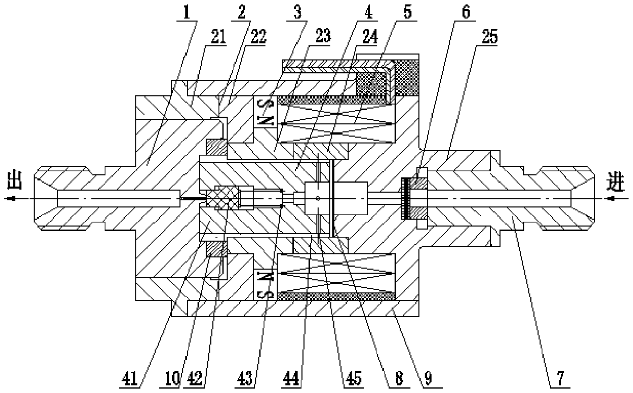
[0019] Such as figure 1 As shown, the embodiment of the present invention provides a small high-pressure self-locking valve, including a valve seat 1, a valve body 2, a permanent magnet 3, a valve core 4, a coil 5, a magnetic isolation gasket 8, a filter 6, and an inlet joint 7 It is connected with the casing 9, the valve seat 1, the valve body 2, the valve core 4, the magnetic isolation gasket 8, the filter 6, and the inlet joint 7 from left to right. The valve body 2 is a welded one-piece struct...


PUM


Abstract

The invention discloses a small-sized high-pressure self-locking valve. The small-sized high-pressure self-locking valve comprises a valve seat, a valve body, permanent magnets, a valve element, coils, magnetism isolation spacers, a filter, an inlet joint and a casing; the valve seat, the valve body, the valve element, the magnetism isolation spacers, the filter and the inlet joint are sequentially connected with one another from left to right; the valve body adopts a welding integral structure and comprises a lower base, magnetism isolation limiting flanges, magnetism conductive sleeves, magnetism isolation rings and an upper base which are sequentially welded with one another from left to right; the permanent magnets are mounted on the outer sides of bosses of the magnetism conductive sleeves of the valve body respectively; the coils are arranged at grooves formed in the outer sides of the valve body; the casing is in a cylinder shape and is assembled by being matched with the upper base and the lower base of the valve body; regulation spacers are symmetrically arranged on two sides of the valve element; the left ends of the regulation spacers are abutted against the valve seat; and the right ends of the regulation spacers are abutted against the magnetism isolation limiting flanges and the magnetism conductive sleeves respectively. Through adoption of the small-sized high-pressure self-lock valve, magnetic circuit design is highly integrated, the service life of the valve is prolonged, and the sealing performance of the valve is improved.

Description

technical field [0001] The invention relates to a self-locking valve for an electric propulsion system and a high-rail propulsion system, in particular to a small high-pressure self-locking valve. Background technique [0002] Based on the characteristics of miniaturization of electric propulsion and high-orbit satellite propulsion systems, the key components used-self-locking valves are required to be small, light, high pressure (23-60MPa), fast response, and long life. At present, the conventional high-pressure self-locking valve is a magnetic locking solenoid structure, which is large in size, heavy in weight, and high in power consumption, and cannot fully meet the requirements of the existing electric propulsion system. Contents of the invention [0003] Aiming at the defects in the prior art, the object of the present invention is to provide a small high-pressure self-locking valve, which has the advantages of small size, light weight, fast response and long life. ...

Claims


Application Information

Patent Timeline
Patent Type & Authority Patents(China)
IPC IPC(8): F16K31/06
CPCF16K31/0644
Inventor 尤罡王莉马海涛赵春云唐妹芳
Owner SHANGHAI INST OF SPACE PROPULSION
Learn More