Positioning device of voice coil motor

A voice coil motor and positioning device technology, applied in focusing devices, optics, cameras, etc., can solve problems such as unfavorable miniaturization of voice coil motors, and achieve breakthroughs in miniaturization, low cost, and easy miniaturization.

Inactive Publication Date: 2006-04-19
VASSTEK INT
View PDF0 Cites 7 Cited by
  • Summary
  • Abstract
  • Description
  • Claims
  • Application Information

AI Technical Summary

Problems solved by technology

[0002] The composition of the traditional technology voice coil motor device, such as Figure 9 As shown, the fixed part is composed of a magnet 911 and soft iron 912, which is used to generate a stable excitation magnetic field in the air gap 913 of the magnetic circuit, and is fixed on the substrate 92. The moving part is a coil 931 wound by an enameled wire. Composed of a power supply cable 932, when the coil 931 passes current, according to Fleming's left-hand rule, the coil 931 will be forced to move to achieve the effect of linear motion, because the coil 931 will move, so the voice coil motor must have A power supply cable 932, one end of the power supply cable 932 must be electrically connected to the coil 931 to supply the coil 931 current, the other end must be electrically connected to the power input contact on the substrate 92, when the coil 931 is a moving part, the power supply cable 932 It must be able to deform accordingly to meet the demand for continuous power supply. Traditional voice coil motors mostly use the U-shaped structure as shown in the figure to achieve this goal. For low-power voice coil motors, they are often made of flexible flexible circuit boards. However, This structure requires a large curvature radius space to maintain the continuous bending life of the power supply cable, which is not conducive to the miniaturization of the voice coil motor; in order to achieve closed-loop positioning control, the device must include a position sensor 94 to detect the sound The displacement of the moving part of the coil motor also includes a positioning controller 95, which is used to adjust the current in the coil 931 of the voice coil motor, so that the relative position between the moving part and the fixed part of the voice coil motor can be controlled. Position sensing technology is also an important topic

Method used


Image

  • Positioning device of voice coil motor
  • Positioning device of voice coil motor
  • Positioning device of voice coil motor

Examples


Embodiment Construction

[0030] Now for each technical content detail of the present invention, obtain better understanding by referring to accompanying drawing through following detailed description:

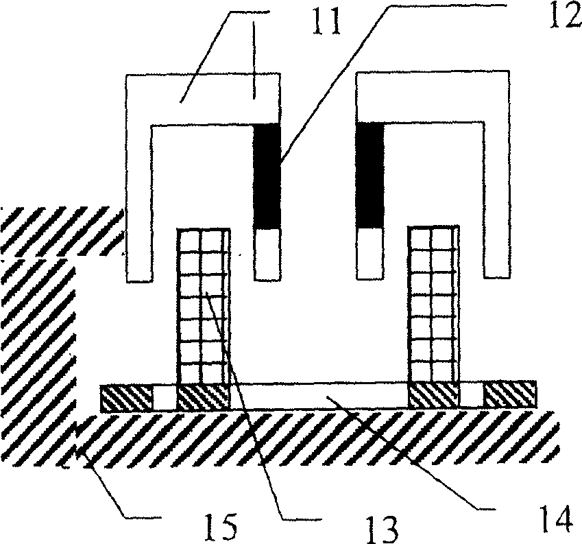
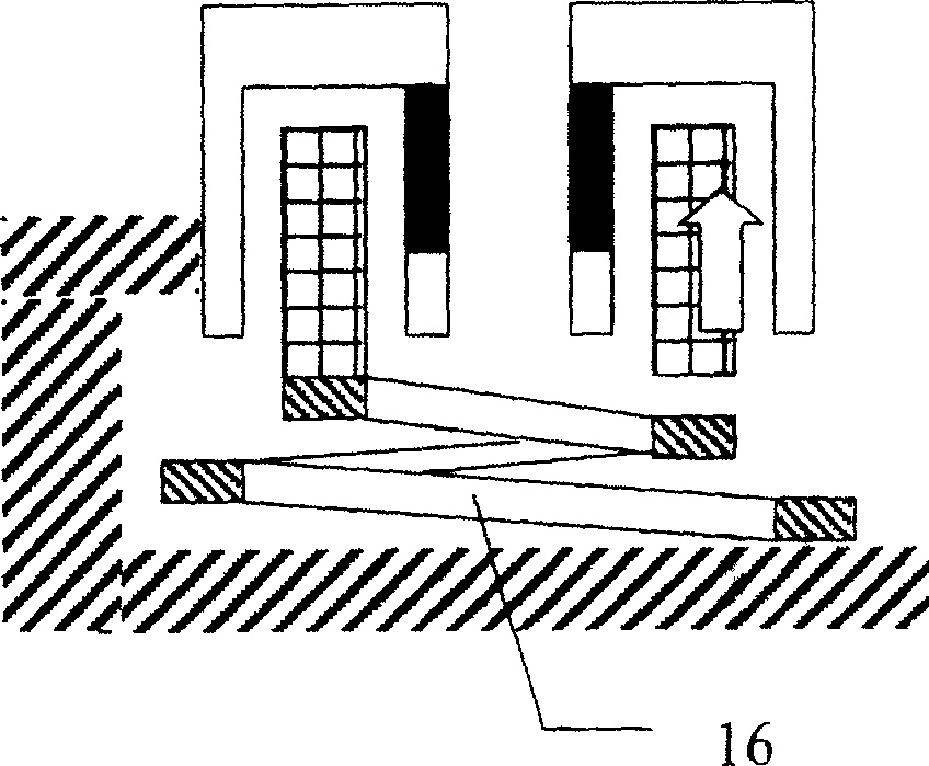
[0031] The voice coil motor in the present invention is movable such as coil, a preferred one, such as Figure 1a As shown, its fixed part is made of soft iron 11 and magnet 12, and is fixed on a base 15, and its moving part is the power supply formed by the flexible circuit board of coil 13 and the invented plate-shaped vortex appearance. When the coil 13 stops at one end, the power supply cable 14 maintains the original flat plate shape, and when the coil 13 moves to the direction of the other stop due to the force of the current flowing, Figure 1b As shown, since one end of the power supply cable 14 is electrically connected to the coil 13 and the other end is electrically connected to the base 15, a deformation 16 similar to a spring will be produced. The deformation approaching an infinite equiv...


PUM


Abstract

The invention is related to a kind of positioning device of voice coil motor, especially to the positioning device of voice coil motor applicable to driving automatic focusing lens group of minitype camera. The device includes a voice coil motor, a position feedback sensor and a positioning controller. If voice coil is a movable piece, then power supply cable is flexible PCB in tabular vortex shape; if voice coil is a fixed piece, then power supply cable is fixed cable. Being composed of a photo interrupter, a light source reflecting plate including full white or black / white combined color blocks, and a specific biasing circuit, the position feedback sensor is in use for detecting continuous displacement of movable piece of voice coil motor. Receiving signal from feedback sensor, through operations of proportion, differentiation and integration, passing through power amplifier, the positioning controller makes voice coil motor controllable precisely.

Description

technical field [0001] The invention relates to a voice coil motor precision positioning device which is easy to be miniaturized, in particular to a voice coil motor positioning device which can be applied to driving an auto-focus lens group of a miniature camera. Background technique [0002] The composition of the traditional technology voice coil motor device, such as Figure 9 As shown, the fixed part is composed of a magnet 911 and soft iron 912, which is used to generate a stable excitation magnetic field in the air gap 913 of the magnetic circuit, and is fixed on the substrate 92. The moving part is a coil 931 wound by an enameled wire. Composed of a power supply cable 932, when the coil 931 passes current, according to Fleming's left-hand rule, the coil 931 will be forced to move to achieve the effect of linear motion, because the coil 931 will move, so the voice coil motor must have A power supply cable 932, one end of the power supply cable 932 must be electrically...

Claims


Application Information

Patent Timeline
Patent Type & Authority Applications(China)
IPC IPC(8): G03B13/36G03B13/32
Inventor 曾有光
Owner VASSTEK INT
Why Eureka
Try Eureka