
Method for treating foundation by vacuum prepressing method through positionable water permeable pipes

A foundation treatment and permeable pipe technology, which is applied in soil protection, infrastructure engineering, construction, etc., can solve the problems of high fluidity, high moisture content of muddy soil, and small water passing area of ​​drainage boards, so as to increase the additional stress Effect

Inactive Publication Date: 2017-06-27
NANJING UNIV OF TECH
View PDF3 Cites 2 Cited by
  • Summary
  • Abstract
  • Description
  • Claims
  • Application Information

AI Technical Summary

Problems solved by technology

[0004] 1. Due to the high water content and high fluidity of muddy soil, especially dredging silt, it is easy to form "mud column", "mud film" and "mud skin" with poor water permeability around the drainage board and cause drainage board silting And other problems, which greatly affected the drainage function of the plastic drainage board
[0005] 2. The silty soil has a high water content, and the deformation is large during the consolidation process. However, due to its low strength, the drainage board is prone to large "S" or "Z" bending deformation in the soil, and even local break off
[0006] 3. Due to the small water passing area of ​​the drainage board, the vacuum degree loses greatly with the depth, and the actual foundation treatment effect is not good
[0007] 4. For the soft soil foundation with a permeable interlayer, the traditional vacuum preloading method needs to set up a sealing wall to ensure the vacuum degree under the sealing film. The process is relatively complicated and the project cost is relatively high

Method used


Image

  • Method for treating foundation by vacuum prepressing method through positionable water permeable pipes
  • Method for treating foundation by vacuum prepressing method through positionable water permeable pipes

Examples


Embodiment Construction

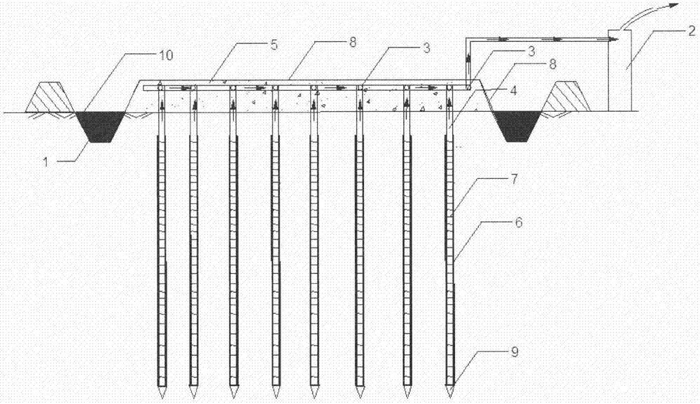
[0030] see figure 1 , a vacuum preloading ground treatment method using positionable permeable pipes, the adopted positionable permeable pipes include ordinary steel pipes 4 , filter screens 6 , lead wires 7 , and back-sealing steel sheets 9 . The steel pipe is drilled with holes with a diameter of Φ10mm and a center distance of 30mm in the designed drainage area. The outside of the steel pipe is wrapped with a filter screen 6 and fixed with a lead wire 7. The bottom of the permeable pipe is welded with a 4.0mm iron plate and covered with a rubber base.

[0031] A vacuum preloading foundation treatment method using a positionable permeable pipe according to the present invention comprises the following steps:

[0032] 1. Large-scale machinery enters the site, leveling the site, and excavating temporary drainage ditches to ensure that the surface water can be led out of the scope of foundation reinforcement treatment in time.

[0033] 2. The measuring engineer uses a level and...


PUM

PropertyMeasurementUnit
Permeability coefficientaaaaaaaaaa

Abstract

The invention discloses a method for treating a foundation by a vacuum prepressing method through positionable water permeable pipes, and belongs to the field of geotechnical engineering. The method comprises the following steps of (1) leveling a site; (2) paving a sand cushion; (3) performing measurement to determine hole positions of the water permeable pipes, and arranging the positionable water permeable pipes to a designed depth in an inserting manner; (4) laying vacuum pipes, and enabling each vacuum pipe to be connected with the corresponding positionable water permeable pipe; (5) laying another sand cushion and a sealing film; (6) enabling a vacuumizing device to be connected with the vacuum pipes; (7) turning on the vacuumizing device to pump out gas and water under the sealing film, and continuing vacuumizing until the vacuumizing device is unloaded; and (8) after the project is completed, recovering the positionable water permeable pipes. The method disclosed by the invention can be flexibly applied in a complex stratum situation, and the flow cross-section of a draining well is enlarged, so that the problems of clogging of plastic draining plates and 'mud columns' formed in the periphery of the plastic draining plates can be solved; and the water permeable pipes can be recovered and utilized, so that the engineering cost is reduced, and the treating effect of the foundation is greatly improved.

Description

technical field [0001] The invention belongs to the field of geotechnical engineering, in particular to the field of foundation treatment, and specifically relates to a vacuum preloading foundation treatment method using a positionable permeable pipe. Background technique [0002] With the rapid development of my country's economy, the shortage of land resources has become increasingly prominent, and many buildings (structures) have to be built on artificial or natural soft soil foundations. Vacuum preloading method has been widely used in soft soil foundation treatment because of its fast reinforcement, short construction period, low cost and simple construction, and the effect is remarkable. [0003] This foundation treatment method mainly changes the original drainage boundary of the foundation and increases drainage channels, so that the soil can be quickly consolidated under the upper atmospheric load to meet the needs of engineering construction. However, the traditio...

Claims


Application Information

Patent Timeline
IPC IPC(8): E02D3/10
CPCE02D3/10
Inventor 刘加才史文韬王旭东
Owner NANJING UNIV OF TECH
Learn More