mmc-hvdc black start simulation test system and test method
A technology of MMC-HVDC, simulation test system, applied in the field of MMC-HVDC black start simulation test system, can solve the problems of inconvenience of residents' daily life, economic loss of enterprises, black start failure and so on
- Summary
- Abstract
- Description
- Claims
- Application Information
AI Technical Summary
Problems solved by technology
Method used
Image
Examples
Embodiment 1
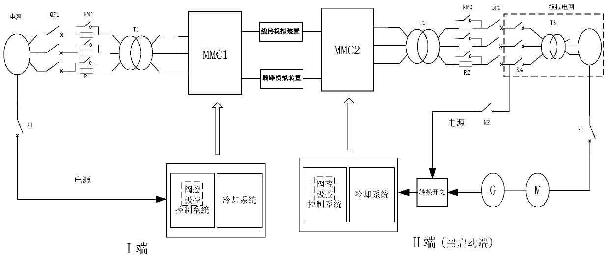
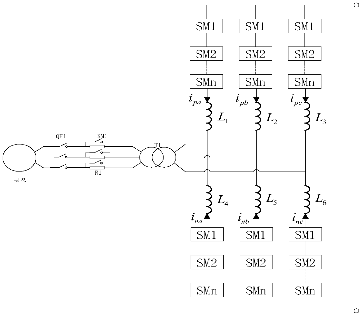
[0032] Such as figure 1 As shown, the MMC-HVDC black start simulation test system includes the I-end converter station system and the II-end converter station system. The I-end converter station system is connected to the II-end converter station system through a line simulation device. The core parts of the station and the converter station at the II end are both MMCs, which are MMC1 and MMC2 respectively. Both the I-end converter station system and the II-end converter station system are real converter systems, and the power grids in the I-end converter station system and the II-end converter station system are both real power grids.
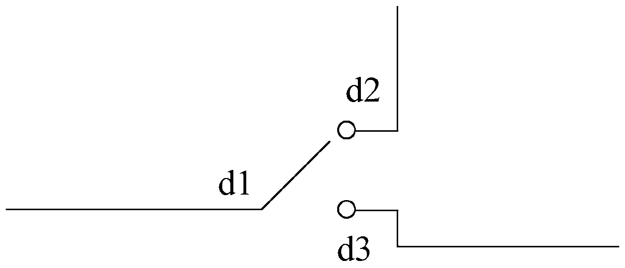
[0033] The first circuit breaker QF1, the first soft start device and the transformer T1 are sequentially connected in series on the connection line between the first power grid and the AC side of the MMC1 in the I-end converter station system, and the MMC2 in the II-end converter station system A transformer T2, a second soft start device, a...
Embodiment 2
[0054] Compared with the above-mentioned embodiment, in this embodiment, the MMC-HVDC black start simulation test system does not include motors and generators, so there is only one way to supply power to the II-side control system—grid, and accordingly, the transfer switch does not need to be set , then, in the black start simulation test method based on this system, there is no relevant step of switching the power supply of the II-side control system.
[0055] Therefore, based on the simulation test system in this embodiment, the black start simulation test method generally includes the following steps:
[0056] (1), disconnect the simulation test switch K4, simulate the power failure of the II terminal system grid, and disconnect the circuit breaker switches QF1 and QF2;
[0057] (2), close the circuit breaker QF1, actively start MMC1, passively start MMC2, and the submodules in these two MMCs start charging;
[0058] (3) After the sub-modules in MMC1 and MMC2 are charged,...
PUM
 Abstract
Description
Claims
Application Information
 - R&D
- Intellectual Property
- Life Sciences
- Materials
- Tech Scout
- Unparalleled Data Quality
- Higher Quality Content
- 60% Fewer Hallucinations
Browse by: Latest US Patents, China's latest patents, Technical Efficacy Thesaurus, Application Domain, Technology Topic, Popular Technical Reports.
© 2025 PatSnap. All rights reserved.Legal|Privacy policy|Modern Slavery Act Transparency Statement|Sitemap|About US| Contact US: help@patsnap.com


