Auxiliary mounting device for automatic automobile instrument producing line
An automatic production line and installation device technology, applied in metal processing, metal processing equipment, manufacturing tools, etc., can solve the problems of low production efficiency, waste of manpower, high production cost, etc., and achieve the goal of improving installation efficiency, improving production efficiency and reducing manpower Effect
- Summary
- Abstract
- Description
- Claims
- Application Information
AI Technical Summary
Problems solved by technology
Method used
Image


Examples
specific Embodiment approach 1
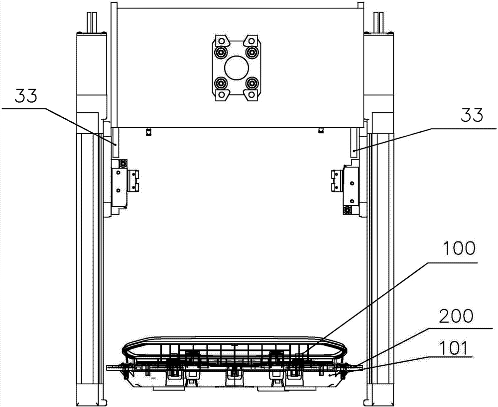
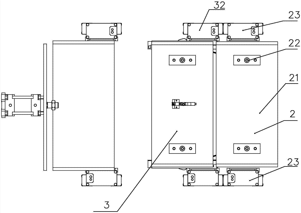
[0020] Specific implementation mode one: combine Figure 1 to Figure 7 Describe this embodiment, an auxiliary installation device for an automated production line of automobile instrumentation, which includes a transmission assembly 1, a press-fit assembly 2 and a vertical movement assembly, the press-fit assembly 2 is arranged above the transmission assembly 1, and the press-fit assembly 2 includes a first sliding table 21, two press-fit cylinders 22 and two first brackets 23 arranged side by side, the first sliding table 21 is arranged between the two first brackets 23, and the first sliding table 21 and the two The first brackets 23 are slidably connected through vertical moving components respectively, and the two press-fit cylinders 22 are fixed vertically on the first slide table 21 , and the piston rod ends of the press-fit cylinders 22 are equipped with a pressure head 24 .
[0021] The screen ring 100 and the bottom case 101 correctly positioned by manual or automated...
specific Embodiment approach 2
[0022] Specific implementation mode two: combination Figure 1-7 To illustrate this embodiment, the press-fit assembly 2 also includes a clamping frame 25 and a plurality of clamping cylinders 26 arranged below the first sliding table 21, and a plurality of clamping cylinders 26 are affixed to the clamping frame 25. The clamping frame 25 is located between the two first brackets 23 , and the clamping frame 25 is slidably connected to the two first brackets 23 through a vertical moving component. In such a design, when the pressing cylinder 22 moves downward to press the screen ring 100 and the bottom case 101, the clamping frame 25 moves downward, and several clamping cylinders 26 move at the same time to clamp the screen ring 100 and the side of the bottom case 101. The buckles are clamped and fixed to ensure that the installation positions of the screen ring 100 and the bottom case 101 are accurate. Other compositions and connections are the same as those in the first embod...
specific Embodiment approach 3
[0023] Specific implementation mode three: combination Figure 5 To describe this embodiment, the number of the clamping cylinders 26 is seven. With such a design, according to the actual situation of the screen ring 100, the position and quantity of the clamping cylinders 26 are reasonably allocated to achieve the best fixed position. The end of the piston rod of the clamping cylinder 26 is fixedly connected with a contact head, and the positioned screen ring and the bottom shell are defined as a mounting part. Uniform force. Other compositions and connections are the same as in the second embodiment.
PUM
 Abstract
Description
Claims
Application Information
 - R&D
- Intellectual Property
- Life Sciences
- Materials
- Tech Scout
- Unparalleled Data Quality
- Higher Quality Content
- 60% Fewer Hallucinations
Browse by: Latest US Patents, China's latest patents, Technical Efficacy Thesaurus, Application Domain, Technology Topic, Popular Technical Reports.
© 2025 PatSnap. All rights reserved.Legal|Privacy policy|Modern Slavery Act Transparency Statement|Sitemap|About US| Contact US: help@patsnap.com