
Surgical operation movable pull hook

A technology of surgical operation and crossbar, which is applied in the fields of surgery and medical science, which can solve the problems of surgical operation obstruction, inability to three-dimensional direction, small adjustable angle, etc., and achieve the effect of increasing stability, easy operation, and good stability

Active Publication Date: 2017-06-23
陕西中医药大学附属医院
View PDF11 Cites 0 Cited by
  • Summary
  • Abstract
  • Description
  • Claims
  • Application Information

AI Technical Summary

Problems solved by technology

The current surgical retractor is generally composed of a hook part and an arm part. The two are usually integrated, and the angle and direction of the two cannot be adjusted according to the needs. There are many deficiencies in the use process.
At present, there are also adjustable surgical retractors, which usually connect the hook and the arm in a hinged manner. The adjustment method is usually limited to one plane, and the adjustable angle is small, and it cannot be adjusted in three dimensions. The surgical field cannot be fully exposed, and sometimes it will cause certain obstacles to the surgical operation
In addition, during the use of the existing surgical retractors, the purpose of pulling the skin and tissues is achieved by pulling, which is often limited by the surgical site, which makes the retractors inconvenient or cannot be fixed firmly, and also brings inconvenience to the surgical operation. some inconvenience
Moreover, the existing retractors cannot meet the needs of all shapes of wounds, which also brings inconvenience to the operation

Method used


Image

  • Surgical operation movable pull hook
  • Surgical operation movable pull hook
  • Surgical operation movable pull hook

Examples


specific Embodiment approach

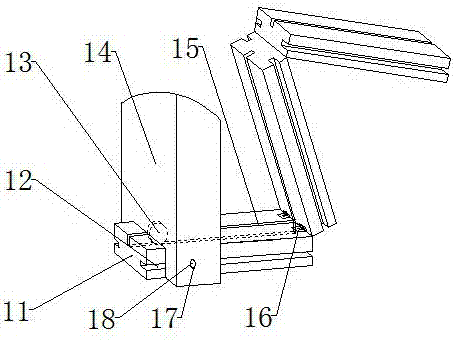
[0024] The specific embodiment: during use, the cuboid blocks 11 are connected successively by the hinge 16, the pole one 8 is fixed on the right end of the support bottom pole 2, the steamboat 13 is installed on the bottom end of the pole two 14, and then the pole two 14 is installed on the upper end surface of the bottom rod 2 of the support, and the second rod 14 is on the left side of the first 8 of the rod, and then the long screw 18 is installed in the threaded hole 17 at the bottom of the second rod 14. When it is necessary to move the second rod 14, turn it Loosen the long screw 18, push the pole 2 14 in the required direction to drive the small wheel 13 to rotate, so that the pole 2 14 moves, and tighten the long screw 18 when fixing, so that the bottom of the long screw 18 contacts the bottom of the positioning groove 12 and generates an interaction force , the design enhances the adaptability of the present invention, realizes movement and positioning quickly, and is...


PUM


Abstract

The invention provides a surgical operation movable pull hook. The surgical operation movable pull hook comprises a support bottom rod, a first support rod, a second support rod, a small wheel, a first long shaft, a second long shaft, a first L-shaped cross rod, a second L-shaped cross rod, a first pull hook, square holes, a semicircular through hole, a round plate and a second pull hook, the support bottom rod is installed at the bottom of a support, the first support rod is fixed at the right end of the support bottom rod, the second support rod is arranged at the left part of the first support rod, the small wheel is installed at the bottom face of the second support rod, the first long shaft is fixed at the upper part of the first support rod, and is installed at the front part of the first L-shaped cross rod, the second long shaft is fixed at the upper part of the second support rod, and is installed at the rear part of the second L-shaped cross rod, the square holes are evenly distributed between the second long shaft and the second L-shaped cross rod, the first pull hook is installed in the square holes, the semicircular through hole is formed in the lower part of the round plate, and the round plate is installed on the cross rod. The surgical operation movable pull hook is convenient to use and operate, good in stability and high in reliability.

Description

technical field [0001] The invention is a movable retractor for surgical operations, which belongs to the field of medical equipment. Background technique [0002] Surgical retractors are used in clinical operations to pull the skin or tissue at the incision so as to fully expose the surgical field. The current surgical retractor generally consists of a hook portion and an arm portion, the two are usually integrated, and the angle and direction of the two cannot be adjusted according to needs, and there are many deficiencies in the use process. At present, there are also adjustable surgical retractors, which usually connect the hook and the arm in a hinged manner. The adjustment method is usually limited to one plane, and the adjustable angle is small, and it cannot be adjusted in three dimensions. The surgical field cannot be fully exposed, and sometimes it will cause certain obstacles to the surgical operation. In addition, during the use of the existing surgical retract...

Claims


Application Information

Patent Timeline
Patent Type & Authority Applications(China)
IPC IPC(8): A61B17/02
CPCA61B17/02
Inventor 李保卫陈嘉豪罗水建
Owner 陕西中医药大学附属医院
Learn More