
Flour processing device with convenient-dismounting stirring shaft

A technology that facilitates disassembly and processing of devices, applied to dough mixers, structural components of mixing/kneading machines, mixing/kneading with vertical installation tools, etc., can solve problems such as increased production costs, inconvenient cleaning, waste of raw materials, etc. Achieve the effect of reducing production cost, convenient work and saving raw materials

Active Publication Date: 2017-06-23
多麦(福建)食品有限公司
View PDF6 Cites 8 Cited by
  • Summary
  • Abstract
  • Description
  • Claims
  • Application Information

AI Technical Summary

Problems solved by technology

[0002] In the prior art: the patent application publication number of CN 106417425 A discloses a flour processing device that facilitates disassembly of the stirring shaft, including a frame, a stirring barrel on the frame, a stirring mechanism in the stirring barrel, and a stirring mechanism under the stirring barrel. The motor and the stirring mechanism include a stirring shaft and a stirring knife mounted on the stirring shaft. The stirring knife includes two sleeves spaced apart in the axial direction. The knife body includes a column fixed on the two sleeves and a blade connected between the two columns. There is a locking screw in the head hole, the lower end of the stirring shaft protrudes from the mixing barrel and is connected to the stirring motor. There are guide grooves on both sides of the frame, and the frame is equipped with a moving bracket that moves along the guide groove. A water tank and a noodle feeding mechanism are installed on the top. The noodle feeding mechanism includes a noodle hopper and a noodle outlet pipe vertically connected to the lower end of the noodle hopper. A feeding screw is arranged inside the noodle outlet pipe. There is a cover on the top, the flour concentration is not easy to control, it cannot meet different processing needs, and it is inconvenient to clean, resulting in waste of raw materials and increasing production costs

Method used


Image

  • Flour processing device with convenient-dismounting stirring shaft
  • Flour processing device with convenient-dismounting stirring shaft

Examples


Embodiment Construction

[0018] The technical solutions in the embodiments of the present invention will be clearly and completely described below in conjunction with the accompanying drawings in the embodiments of the present invention. Obviously, the described embodiments are only a part of the embodiments of the present invention, rather than all the embodiments. Based on the embodiments of the present invention, all other embodiments obtained by those of ordinary skill in the art without creative work shall fall within the protection scope of the present invention.

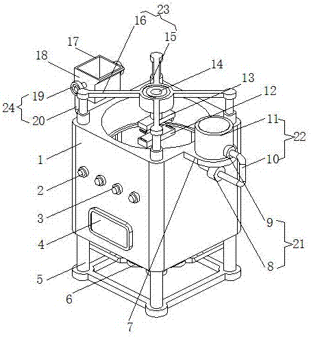
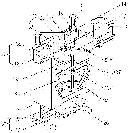
[0019] See Figure 1-2 , The present invention provides a technical solution: a flour processing device that facilitates disassembly of the mixing shaft, comprising a box body 1, one side of the box body 1 is connected with a feeding device 17 through a swing mechanism 24, and the other side of the box body 1 is welded with Connecting ear 7, a water injection device 22 is installed on the top of the connection ear 7, and the water inject...


PUM


Abstract

The invention discloses a flour processing device with a convenient-dismounting stirring shaft. The device comprises a box body, wherein a feeding device is connected to one side of the box body through a swinging mechanism, and a connecting lug is welded to the other side of the box body; a water pouring device which communicates with the inside of the box body is mounted at the top part of the connecting lug; and a quantity control device is mounted on the water pouring device. According to the flour processing device with the convenient-dismounting stirring shaft, the stirring shaft is mounted by clamping through a clamping mechanism, and a lifting mechanism is arranged, so that the stirring shaft can be conveniently dismounted and maintained; residual raw materials on the inner wall of the box body can be swept through a sweeping device, so that the cleanness and the convenience are ensured, and the raw materials can be saved; in addition, the production cost is decreased; the feeding device capable of easily controlling the quantity, the quantity control device and a concentration detecting device are arranged to adjust and control the concentration of paste to meet different processing demands, and thus related workers can work conveniently.

Description

Technical field [0001] The invention relates to the technical field of flour processing devices, in particular to a flour processing device that is convenient to disassemble a mixing shaft. Background technique [0002] In the prior art: The patent with application publication number CN 106417425 A discloses a flour processing device that is convenient to disassemble the mixing shaft, including a frame, a mixing barrel on the frame, a mixing mechanism in the mixing barrel, and a stirring under the mixing barrel. The motor and the stirring mechanism include a stirring shaft and a stirring knife mounted on the stirring shaft. The stirring knife includes two sleeves spaced axially. The knife body includes a column fixed on the two sleeves, a blade connected between the two columns, There is a locking screw in the head hole, the lower end of the mixing shaft extends out of the mixing barrel and is connected to the mixing motor. The two sides of the frame are equipped with guide groov...

Claims


Application Information

Patent Timeline
Patent Type & Authority Applications(China)
IPC IPC(8): A21C1/02A21C1/14
CPCA21C1/02A21C1/14A21C1/1405A21C1/1425
Inventor 李占福
Owner 多麦(福建)食品有限公司
Learn More