
Radiological imaging device occupying a reduced space

A technology of radiographic imaging, equipment, applied in the direction of instruments, applications, radiation safety devices for radiological diagnosis, which can solve the problems of increased time length, patient problems, and complicated processes

Active Publication Date: 2017-06-20
IMAGINALIS SRL
View PDF5 Cites 6 Cited by
  • Summary
  • Abstract
  • Description
  • Claims
  • Application Information

AI Technical Summary

Problems solved by technology

The process is further complicated if further surgery is indicated from the radiography, in which case the patient may need to be moved back to the operating room
Furthermore, such transfers often cause problems for patients and therefore require special care and expertise to perform
As a result, the length of time required to perform the above transfers increases

Method used


Image

  • Radiological imaging device occupying a reduced space
  • Radiological imaging device occupying a reduced space
  • Radiological imaging device occupying a reduced space

Examples


Embodiment Construction

[0026] Each of the features and teachings disclosed herein can be utilized alone or in combination with the other features and teachings to provide a radiation imaging apparatus with a reduced footprint. Representative examples employing a number of these additional features and teachings, both individually and in combination, are described in more detail with reference to the accompanying drawings. This specific description is only used to teach those skilled in the art how to practice the teachings of the present invention, but not to limit the scope of the claims. Thus, combinations of above-described features in the detailed description are not necessary to practice the teaching in the broadest sense, but are instead specifically described to represent representative examples of the teachings.

[0027] In the following description, for purposes of explanation only, specific terms are listed to provide a thorough understanding of the present disclosure. It will be apparent...


PUM


Abstract

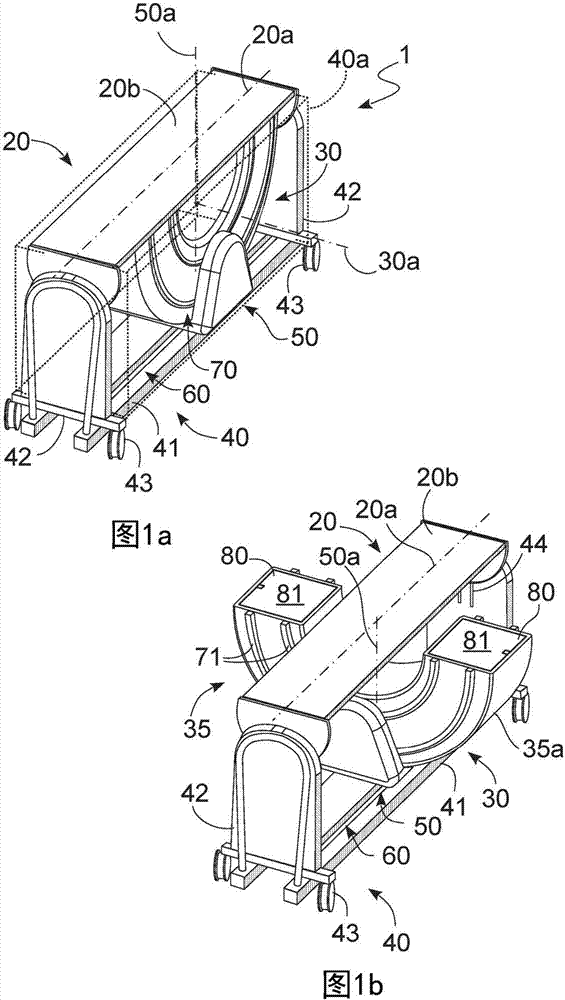
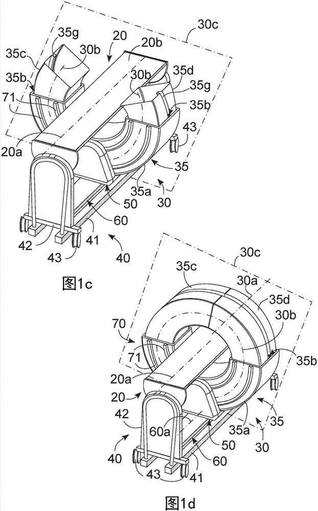
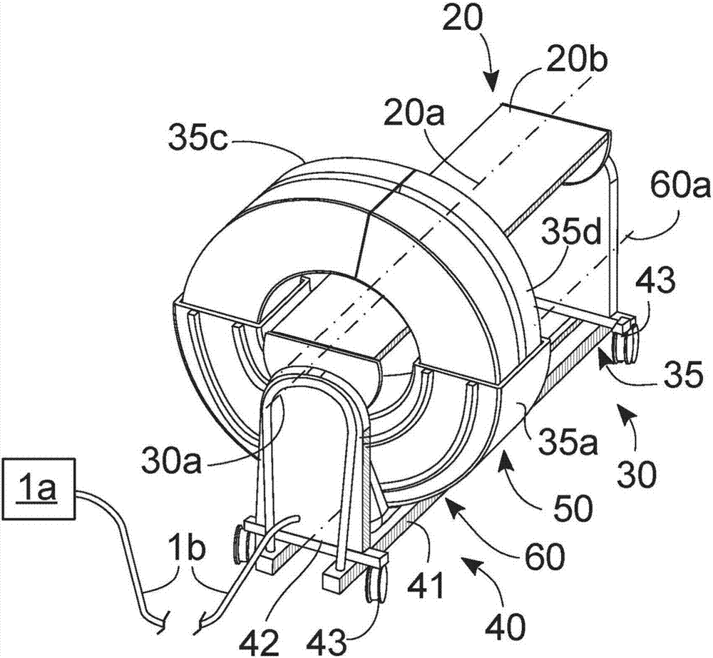
A radiological imaging device (1) comprising a bed (20) defining a main direction (20a); a load-bearing structure (40) suitable to support the bed (20) in a raised position defining a free chamber (40a) between the load-bearing structure (40) and the bed (20); a gantry (30) suitable to perform the radiological imaging; defining a circular trajectory of expansion (30b) lying on a positioning plane (30c); and a rotation mechanism (50) suitable to rotate said gantry (30) in relation to said bed (20) and to said load-bearing structure (40) varying the inclination of said positioning plane (30c) in relation to said main direction (20a); the gantry (30) comprises a source (31) able to emit a radiation; a detector (32) able to receive the radiation after it has traversed the bed (20); and a casing (35) suitable internally to house the source (31) and the detector (32) and comprising a static arched module (35a) connected to the rotation mechanism (50), a mobile arched module (35c, 35d) and a kinematic expansion mechanism (35b) able to move the mobile arched module (35c, 35d) with respect to the static arched module (35a) so as to vary the angular extension of said casing (35) and said gantry (30).

Description

technical field [0001] Exemplary aspects herein relate to a radiographic apparatus comprising: a bed defining a main direction; a load carrying structure adapted to support the bed in a raised position defining a free space between the load carrying structure and the bed; a table , suitable for performing radiographic imaging, defines an elongated circular trajectory lying in the positioning plane. [0002] In particular, at least some of the exemplary aspects herein relate to a special device useful in the medical / veterinary field to obtain images of at least a portion of a patient's internal anatomy for analysis, diagnosis, or other assessments. Background technique [0003] Radiation imaging equipment currently on the market is known to have a standard structure comprising: a bed on which a patient is positioned so that an image scan of the patient is performed; device. [0004] Given the need to contain sources, detectors and moving equipment, the gantry is bulky and ...

Claims


Application Information

Patent Timeline
Patent Type & Authority Applications(China)
IPC IPC(8): A61B6/03A61B6/04A61B6/10
CPCA61B6/035A61B6/0407A61B6/102A61B6/4405A61B6/4452
Inventor D·福尔图那L·马内蒂
Owner IMAGINALIS SRL
Learn More