
Heat management device and power supply device

A power supply device and thermal management technology, applied in the direction of circuits, electrical components, secondary batteries, etc., can solve the problems of power battery discharge performance interference, difficulty in meeting charging and discharging requirements, affecting power battery life and battery capacity, etc.

Pending Publication Date: 2017-06-20
HUATING HEFEI POWER TECH
View PDF9 Cites 5 Cited by
  • Summary
  • Abstract
  • Description
  • Claims
  • Application Information

AI Technical Summary

Problems solved by technology

The power battery will generate a lot of heat when it is working. If the heat cannot be discharged in time, the temperature inside the power battery will continue to rise, causing the internal temperature difference to gradually increase, and eventually the power battery will be in a working environment with a large temperature difference. Medium, affecting the service life of the power battery
Especially in the hot summer, the temperature of the natural environment is very high. If the power battery cannot be effectively managed in a timely manner, its final working temperature will be much higher than the reasonable working temperature of the power battery, which will seriously affect the service life of the power battery and Battery capacity, but also cause greater interference to the discharge performance of the power battery
In addition, the charge and discharge performance of power batteries in low temperature working environments is poor, especially in the cold winter, and it is difficult to meet the necessary charge and discharge requirements.

Method used


Image

  • Heat management device and power supply device
  • Heat management device and power supply device
  • Heat management device and power supply device

Examples


Embodiment Construction

[0027] In order to make the purpose, technical solutions and advantages of the embodiments of the present invention clearer, the technical solutions in the embodiments of the present invention will be clearly and completely described below in conjunction with the drawings in the embodiments of the present invention. Obviously, the described embodiments It is a part of embodiments of the present invention, but not all embodiments. The components of the embodiments of the invention generally described and illustrated in the figures herein may be arranged and designed in a variety of different configurations.

[0028] It should be noted that like numerals and letters denote similar items in the following figures, therefore, once an item is defined in one figure, it does not require further definition and explanation in subsequent figures.

[0029] In the description of the present invention, it should be noted that the orientation or positional relationship indicated by the terms...


PUM


Abstract

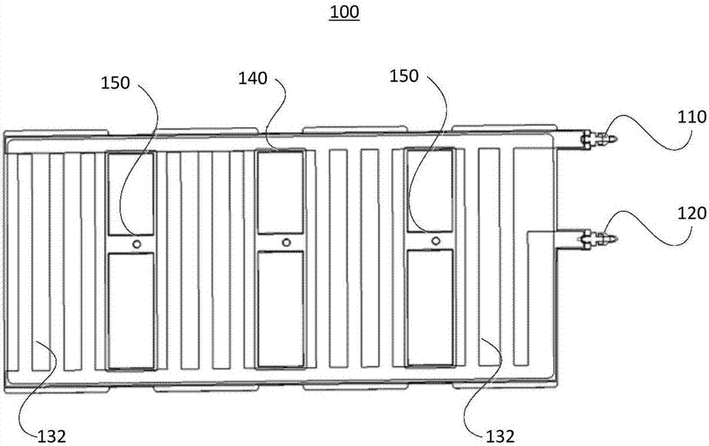
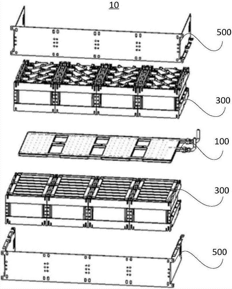
The invention relates to the technical field of battery heat management, in particular to a heat management device and a power supply device. The heat management device is applied to the power supply device comprising a plurality of battery modules. The heat management device comprises a liquid inlet pipe, a liquid outlet pipe and a plurality of heat management assemblies with sealed cavities. The two adjacent heat management assemblies are connected; the liquid inlet pipe and the liquid outlet pipe are arranged at the heat management assembly; a roundabout liquid circulation passage is arranged in each sealed cavity; the liquid circulation passages are formed through separation by a plurality of water passage separation plates arranged in the sealed cavities; the liquid inlet pipe communicates with the liquid outlet pipe through the liquid circulation passages; liquid flows into the liquid circulation passage through the liquid inlet pipe, and then flows out through the liquid outlet pipe for performing heat management on each single battery in each battery module. Through the arrangement, each battery module in the power supply device works in a relatively good charging and discharging temperature state; the service life of the power supply device is prolonged; the performance of the power supply device is improved; the electric energy output stability and the safety reliability of the power supply device are ensured.

Description

technical field [0001] The present invention relates to the technical field of battery thermal management, in particular, to a thermal management device and a power supply device. Background technique [0002] In recent years, due to the increasingly prominent problems of energy costs and environmental pollution, pure electric vehicles and hybrid vehicles have attracted the attention of the government and various automobile companies because of their advantages of greatly eliminating or even zero-emission vehicle exhaust. However, pure electric and hybrid vehicles still have many technical problems to be overcome, and battery service life and capacity fading are one of the important problems. [0003] The service life and capacity fading of the battery are closely related to the temperature difference and temperature rise of the battery module. The power battery will generate a lot of heat when it is working. If the heat cannot be discharged in time, the temperature inside ...

Claims


Application Information

Patent Timeline
IPC IPC(8): H01M10/613H01M10/615H01M10/625H01M10/6568H01M2/10H01M10/6556H01M50/249
CPCH01M10/613H01M10/615H01M10/625H01M10/6556H01M10/6568H01M50/20Y02E60/10
Inventor 张亮李德连袁承超周鹏
Owner HUATING HEFEI POWER TECH
Learn More