
Segmental shaping device and method of round soldering strip and series welding machine

A technology of shaping device and circular welding, applied in auxiliary devices, welding equipment, electrical components, etc., can solve the problems of many seams, cost reduction, and reduction of battery string occupied area.

Active Publication Date: 2017-06-20
宁夏小牛自动化设备股份有限公司 +2
View PDF6 Cites 4 Cited by
  • Summary
  • Abstract
  • Description
  • Claims
  • Application Information

AI Technical Summary

Problems solved by technology

[0004] Therefore, the module manufacturers have thought of leaving no gaps in the connection of the cells or stacking the connecting sections of the cells without welding, especially in the half-cell module of the dense grid, due to the reduction of the cells, the seams between the cells are It seems a bit too much, which reduces the light-receiving area of ​​the module, which affects the power of the module, and because the cost of the battery sheet decreases, the cost of the battery sheet in the module is reduced, so the connection of the battery sheet does not leave a gap or the battery sheet It is particularly critical that the joints are not welded. This method not only reduces the occupied area of ​​the battery string of the module, but also increases the light-receiving surface of the battery sheet, and improves the utilization rate of the solder ribbon, which greatly improves the efficacy of the module. The use of round ribbons for the connection between cells still cannot avoid the cracking phenomenon caused by the lamination process

Method used


Image

  • Segmental shaping device and method of round soldering strip and series welding machine
  • Segmental shaping device and method of round soldering strip and series welding machine
  • Segmental shaping device and method of round soldering strip and series welding machine

Examples


Embodiment Construction

[0031] In order to more clearly illustrate the technical solutions of the embodiments of the present invention, the following will briefly introduce the accompanying drawings that need to be used in the embodiments. Obviously, the accompanying drawings in the following description are some embodiments of the present invention. Ordinary technicians can also obtain other drawings based on these drawings on the premise of not paying creative work.

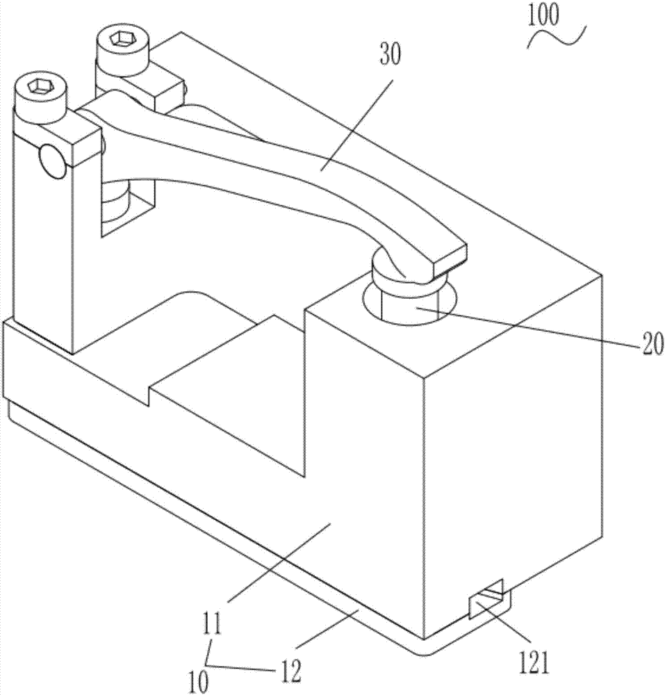
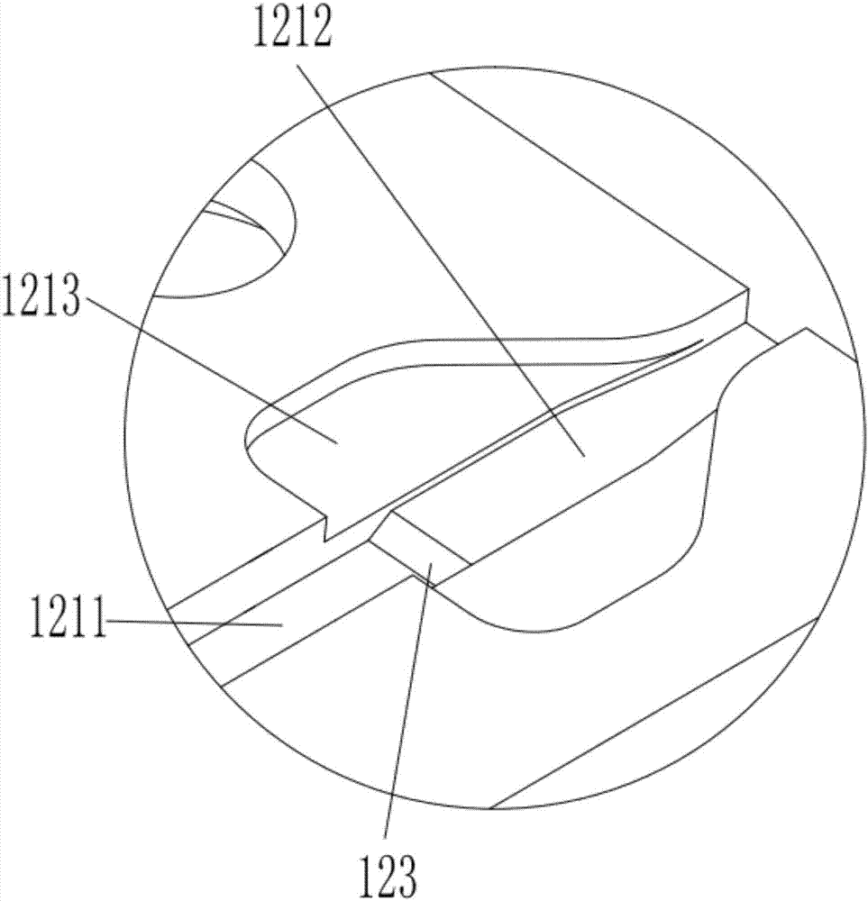
[0032] see Figure 1 to Figure 9 , the embodiment of the present invention provides a circular welding ribbon section shaping device 100, including a base 10, a first driving mechanism 20 and a shaping mechanism 30, the bottom of the base 10 is provided with a welding ribbon channel 121 for passing the welding ribbon , one end of the shaping mechanism 30 is overlapped with the first driving mechanism 20, and the other end of the shaping mechanism 30 is arranged above the ribbon channel 121 at the bottom of the base 10, so that the fir...


PUM


Abstract

A segmental shaping device of a round soldering strip comprises a base, a first driving mechanism and a shaping mechanism, wherein a soldering strip passage is arranged at the bottom of the base and is used for the soldering strip to pass through, one end of the shaping mechanism is overlapped with the first driving mechanism, the other end of the shaping mechanism is arranged above the soldering strip passage at the bottom of the based so that the shaping mechanism is driven to vertically move relative to the base by the first driving mechanism and the shaping of the round soldering strip arranged under the shaping mechanism is further implemented by an acting force between the bottom of the shaping mechanism and the bottom of the base. The driving mechanism drives the shaping mechanism to vertically move, and the shaping of the soldering strip in the soldering strip passage at the bottom of the base is further implemented; and the round soldering strip shaped by employing the method is used for connection between dense-grating battery pieces and connection between half battery pieces, so that the battery pieces and the soldering strip of a battery piece connection segment are flat, and the battery pieces and the battery piece connection segment can be effectively prevented from broken during the lamination process.

Description

technical field [0001] The invention relates to the technical field of ribbon shaping for solar cells, in particular to a segmental shaping device and method for circular ribbons and a stringer. Background technique [0002] With the rapid development of the component industry, the improvement of component power has been paid more and more attention by various component manufacturers. [0003] Nowadays, it is found that the power of cut slices of various cells is higher than that of the whole cell, such as half or 1 / 4, 3 / 4 of three-bar, four-bar, five-bar cells, etc. The test shows that, The power of the crystalline silicon dense grid cell can be increased by 2%-3% compared with the four-gate and five-gate cell components, and the power of the half-cell component of this dense-gate cell is 2%-2.5% higher than that of the whole component. Therefore, While using dense-grid solar cells, the dense-grid half-cell is favored by various component manufacturers. Therefore, the roun...

Claims


Application Information

Patent Timeline
IPC IPC(8): H01L31/18B23K3/08
CPCB23K3/08H01L31/18Y02P70/50
Inventor 王小牛马成虎
Owner 宁夏小牛自动化设备股份有限公司
Learn More