
Hardware watchdog logic circuit

A logic circuit and watchdog technology, applied in the field of hardware watchdog logic circuit, can solve the problems of inability to monitor external equipment and external environmental shocks, and the system cannot maintain the reset signal, etc., to achieve low price, work stability assurance, control simple effect

Pending Publication Date: 2017-06-20
SHENZHEN EMDOOR DIGITAL TECH
View PDF6 Cites 10 Cited by
  • Summary
  • Abstract
  • Description
  • Claims
  • Application Information

AI Technical Summary

Problems solved by technology

[0002] Many existing smart ARM and CPU solutions only have software reset. Software reset is a virtual watchdog algorithm simulated by software. When the program runs away, it will automatically enter the watchdog state; self-timed, if it exceeds a certain period of time, it will be considered that the running program code is wrong Send a reset signal by itself; this virtual watchdog algorithm can only monitor whether the software itself is crashed, and cannot monitor the impact of external equipment and the external environment on the power supply and other systems
If the power supply system crashes, the power supply is not normal, the software cannot judge whether other systems have crashed through the algorithm, or its own power supply is abnormally cut off, and its own system cannot maintain and automatically send a reset signal; it is very unsuitable for smart tablets that have been working for a long time. ), such as smart refrigerators, advertising machines, monitoring equipment, etc., these devices have to work for a long time. Equipment working in a harsh environment requires a longer time to ensure work, and it is impossible to monitor whether the equipment is normal manually. Therefore, a stable gate logic circuit is urgently needed to realize automatic hard reset, so that the machine can return to the working state in time

Method used


Image

  • Hardware watchdog logic circuit
  • Hardware watchdog logic circuit
  • Hardware watchdog logic circuit

Examples


Embodiment Construction

[0015] The present invention will be described in further detail below in conjunction with the accompanying drawings and embodiments.

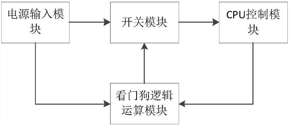
[0016] Such as figure 1 As shown, the present invention includes a power input module, a switch module, a CPU control module and a watchdog logic operation module, and the output terminals of the power input module are respectively connected to the input terminals of the switch module and the input terminals of the watchdog logic operation module. The output terminal of the switch module supplies power to the CPU control module, and the output terminal of the CPU control module is connected to the input terminal of the watchdog logic operation module, and the watchdog logic operation module controls the closing and closing of the switch module.

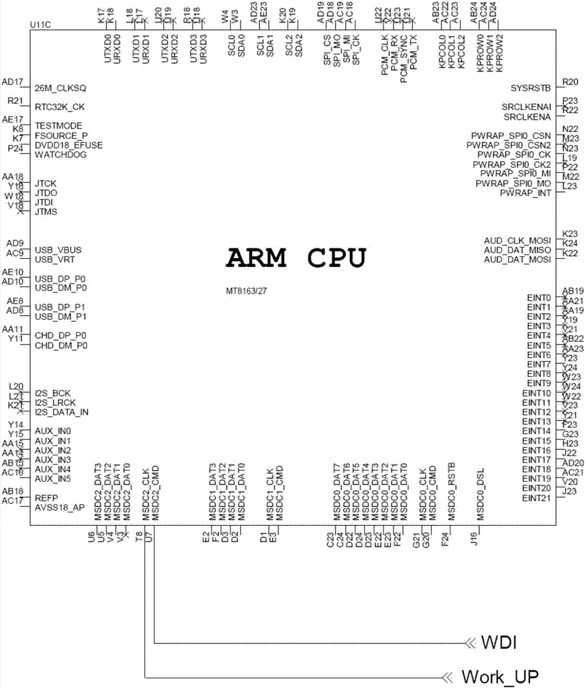
[0017] Such as figure 2 As shown, the input terminal of the power input module is a stable 5V DC power supply input by an external power adapter or a machine distribution power supply. The power inp...


PUM


Abstract

The invention provides a hardware watchdog logic circuit and belongs to the field of power supply control circuits. The hardware watchdog logic circuit comprises a power supply input module, a switch module, a CPU control module and a watchdog logic operation module. The output end of the power supply input module is separately connected with the input end of the switch module and the input end of the watchdog logic operation module, the output end of the switch module supplies power to the CPU control module, and the output end of the CPU control module is connected with the input end of the watchdog logic operation module which controls the closing and opening of the switch module. The hardware watchdog logic circuit has the advantages of being easily controlled, having few electronic components, being low in price and mainly used in intelligent equipment working in severe environments and needing to work for a long time, providing a guarantee for work stability of intelligent refrigerators, advisement players, monitoring equipment and other intelligent equipment working for a long time, and being capable of ensuring that the equipment is quickly restored to a normal work state after crash.

Description

technical field [0001] The invention relates to a power supply control circuit, in particular to a hardware watchdog logic circuit. Background technique [0002] Many existing smart ARM and CPU solutions only have software reset. Software reset is a virtual watchdog algorithm simulated by software. When the program runs away, it will automatically enter the watchdog state; self-timed, if it exceeds a certain period of time, it will be considered that the running program code is wrong Just send a reset signal by itself; this kind of virtual watchdog algorithm can only monitor whether the software itself is crashed, and cannot monitor the impact of external equipment and the external environment on the power supply and other systems. If the power supply system crashes, the power supply is not normal, the software cannot judge whether other systems have crashed through the algorithm, or its own power supply is abnormally cut off, and its own system cannot maintain and automatic...

Claims


Application Information

Patent Timeline
IPC IPC(8): G06F11/14
CPCG06F11/1441
Inventor 马保军范德业程文辉
Owner SHENZHEN EMDOOR DIGITAL TECH
Learn More