
Touch control display panel and touch control display device

A technology of touch display panel and display area, applied in the field of touch display device and touch display panel, can solve problems such as unfavorable preparation, disconnection of touch wiring and the like

Active Publication Date: 2017-06-20
SHANGHAI TIANMA MICRO ELECTRONICS CO LTD
View PDF3 Cites 51 Cited by
  • Summary
  • Abstract
  • Description
  • Claims
  • Application Information

AI Technical Summary

Problems solved by technology

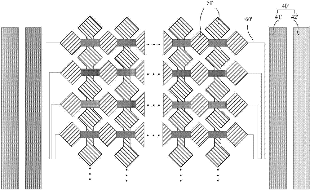
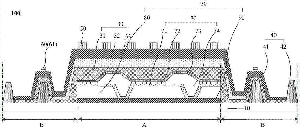
If the touch wiring 60' crosses the first barrier wall 41' and is made between the first barrier wall 41' and the second barrier wall 42', it needs to cross a large step difference h2', which is likely to cause the touch wiring 60' 'Disconnection is not conducive to preparation

Method used


Image

  • Touch control display panel and touch control display device
  • Touch control display panel and touch control display device
  • Touch control display panel and touch control display device

Examples


Embodiment Construction

[0026] In order to make the above objects, features and advantages of the present invention more comprehensible, the present invention will be further described below in conjunction with the accompanying drawings and embodiments. Example embodiments may, however, be embodied in many forms and should not be construed as limited to the embodiments set forth herein; rather, these embodiments are provided so that this disclosure will be thorough and complete, and will fully convey the concept of example embodiments to those skilled in the art. The same reference numerals denote the same or similar structures in the drawings, and thus their repeated descriptions will be omitted. The words expressing position and direction described in the present invention are all described by taking the accompanying drawings as an example, but changes can also be made according to needs, and all changes are included in the protection scope of the present invention. The accompanying drawings of th...


PUM

PropertyMeasurementUnit
Widthaaaaaaaaaa
Heightaaaaaaaaaa
Widthaaaaaaaaaa

Abstract

The invention discloses a touch control display panel and a touch control display device. The panel comprises a substrate, an organic luminescent device, at least one baffles, wherein the width of the at least one baffle is 30-200 micrometers, a thin film encapsulation layer, wherein the thin film encapsulation layer covers the at least one baffle, and difference between the baffle 30 and baffle 40 of the thin film encapsulation layer between the first baffle 41 and a display area A is 0-3 micrometers, electrode wires which are located at least at the non-display area of the substrate, and at least part of the electrode wires are located at the side away from the baffle, of the thin film encapsulation layer, and are arranged in the extension direction of the baffle. The projection of the electrode wires on the substrate is located in the range of the projection of the baffle on the substrate. According to the touch control display panel, at least part of electrode wires are located at the side away from the baffle, of the thin film encapsulation layer, and arranged in the extension direction of the baffle, therefore the side frame area of the baffle location is fully utilized to achieve narrow side frames and the lowering of wire cutting-off risk.

Description

technical field [0001] The present invention relates to the field of touch display, in particular to a touch display panel and a touch display device including the touch display panel. Background technique [0002] With the continuous development of mobile terminal technology, a display screen with a touch function has gradually become a mainstream screen configured in various mobile terminals. The technical principle of the touch panel is that when a finger or other medium touches the screen, it detects voltage, current, sound waves or infrared rays according to different sensing methods, so as to measure the coordinate position of the touch point. [0003] figure 1 It is a structural schematic diagram of a touch display panel in the prior art, figure 2 It is a top view structural diagram of a touch display panel in the prior art, including a substrate 10', a light emitting device 20', a thin film encapsulation layer 30', a barrier 40', a touch electrode 50' and a touch ...

Claims


Application Information

Patent Timeline
IPC IPC(8): G06F3/044
CPCG06F3/044G06F2203/04103H10K59/873G06F3/0412G06F3/0445G06F3/0446H10K59/40H10K59/122H10K59/131H10K50/8426H10K50/844G06F2203/04111G06F2203/04112
Inventor 曾洋周星耀王丽花姚绮君
Owner SHANGHAI TIANMA MICRO ELECTRONICS CO LTD
Learn More