
Air conditioner and heating water system

A technology for cooling and heating air conditioners and heating water, which is applied in air conditioning systems, heating methods, lighting and heating equipment, etc., can solve problems such as power waste and complex structure, and achieve the effects of saving power, convenient control, and convenient water tanks.

Inactive Publication Date: 2017-06-20
武汉崇文新科技有限公司
View PDF7 Cites 0 Cited by
  • Summary
  • Abstract
  • Description
  • Claims
  • Application Information

AI Technical Summary

Problems solved by technology

[0002] Integrated home improvement can integrate air conditioning and hot water into a whole, but the overall structure of the existing air conditioning and hot water systems is complicated. When the system is turned on, it runs as a whole, and when the system is turned off, it is turned off as a whole, and separate control of hot water and air conditioning cannot be realized. , resulting in a huge waste of electric energy

Method used


Image

  • Air conditioner and heating water system

Examples


specific Embodiment 1

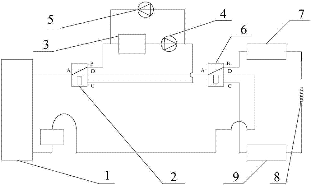
[0017] Specific embodiment one: when the first four-way valve 2 is closed, the input port A of the first four-way valve 2 communicates with the first return port B, and the second return port of the first four-way valve 2 C communicates with the output port D; when the first four-way valve 2 is opened, the input port A of the first four-way valve 2 communicates with the second return port C, and the first four-way valve 2 of the first The return port B communicates with the output port D. In this specific embodiment one: when the temperature in the water tank does not reach the preset temperature, the water in the water tank needs to be heated at this time, the first four-way valve 2 is closed, and the refrigerant medium coming out of the compressor 1 passes through the first four-way valve. The input port A of the through valve 2 flows into the first four-way valve 2, and then flows out from the first return port B of the first four-way valve 2, flows through the water tank 3...

specific Embodiment 2

[0018] Specific embodiment 2: when the first four-way valve 2 is opened, the input port A of the first four-way valve 2 communicates with the first return port B, and the second return port of the first four-way valve 2 C communicates with the output port D; when the first four-way valve 2 is closed, the input port A of the first four-way valve 2 communicates with the second return port C, and the first four-way valve 2 of the first The return port B communicates with the output port D. The working principle of the second embodiment of the present invention is the same as that of the first embodiment of the present invention, except that the switching direction of the first four-way valve 2 is different.

[0019] In specific embodiment 1 or specific embodiment 2 of the present invention: the first heat exchanger 7 is an evaporator, and the second heat exchanger 9 is a condenser; or, the first heat exchanger 7 is Condenser, the second heat exchanger 9 is an evaporator. The re...


PUM


Abstract

The invention relates to an air conditioner and a heating water system. The air conditioner comprises a compressor, a first four-way valve, a water tank, a first one-way valve, a second one-way valve, a second four-way valve, a first heat exchanger, a throttling capillary tube and a second heat exchanger; the output end of the compressor is connected to the input end A of the first four-way valve, the water tank and the first one-way valve are connected between the first backflow end B of the first four-way valve and the second backflow end C of the first four-way valve in series, the flowing direction of a refrigerant is controlled by the first one-way valve and is from the first backflow end B of the first four-way valve to the second backflow end C of the first four-way valve, and the flowing direction of the refrigerant is controlled by the second one-way valve and is from the second backflow end C of the first four-way valve to the first backflow end B of the first four-way valve. Follow-up heating and cooling of the air conditioner cannot be influenced when the water tank works or does not work, the water tank is conveniently controlled, and electric energy is saved.

Description

technical field [0001] The invention relates to the field of integrated home improvement, in particular to a heating and cooling air conditioner and water heating system. Background technique [0002] Integrated home improvement can integrate air conditioning and hot water into a whole, but the overall structure of the existing air conditioning and hot water systems is complicated. When the system is turned on, it runs as a whole, and when the system is turned off, it is turned off as a whole, and separate control of hot water and air conditioning cannot be realized. , resulting in a huge waste of electric energy. Contents of the invention [0003] The technical problem to be solved by the present invention is to provide a heating and cooling air-conditioning and heating water system which is convenient to control and saves electric energy. [0004] The technical solution of the present invention to solve the above-mentioned technical problems is as follows: a cooling and...

Claims


Application Information

Patent Timeline
Patent Type & Authority Applications(China)
IPC IPC(8): F24F5/00F25B13/00F25B41/04F25B41/20F25B41/24
CPCF24F5/0096F25B13/00F24F2221/18F25B2600/25F25B2313/0292F25B2313/02742F25B41/20
Inventor 夏涛
Owner 武汉崇文新科技有限公司
Learn More