
Unmanned aerial vehicle flight landing system and method based on image processing

A technology of image processing and drones, which is applied to unmanned aircraft, aircraft, motor vehicles, etc., can solve the problems of high power consumption of algorithms, heavy weight of cameras, and the impact of precise landing of drones, etc., to achieve precise positioning , fast landing speed, and the effect of securing the position

Active Publication Date: 2017-06-20
SHANDONG UNIV +1
View PDF5 Cites 23 Cited by
  • Summary
  • Abstract
  • Description
  • Claims
  • Application Information

AI Technical Summary

Problems solved by technology

[0004] First, in the existing technology, the camera is installed on the drone, and the drone is equipped with the camera to take pictures of the surroundings and decide whether the drone lands. This puts higher requirements on the drone, because the camera itself The weight is relatively heavy, the weight of the drone itself, the weight of the battery, and the weight of the camera. For the drone, a heavy battery is needed to ensure the round trip of the drone; the camera is installed on the drone Affect the cruising distance of the UAV;
[0005] Second, the calculation process of the existing technology is all on the UAV, and the UAV performs the calculation of the algorithm. The algorithm requires a lot of power consumption, which also poses a great challenge to the battery of the UAV;
[0006] Third, the camera of the prior art is installed on the UAV. If the UAV encounters a windy and sandy environment during the flight, it will cause the UAV to fly unstable, thereby affecting the camera's camera angle and camera accuracy, thereby affecting the quality of the camera. The precision landing of drones has an impact

Method used


Image

  • Unmanned aerial vehicle flight landing system and method based on image processing
  • Unmanned aerial vehicle flight landing system and method based on image processing
  • Unmanned aerial vehicle flight landing system and method based on image processing

Examples


Embodiment Construction

[0121] The present invention will be further described below in conjunction with the accompanying drawings and embodiments.

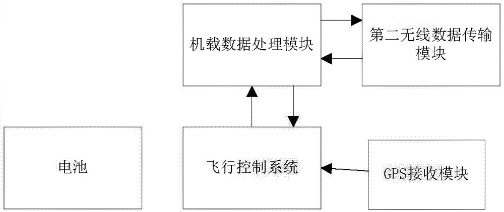
[0122] Such as figure 1 As shown, the ground-guided UAV flight and landing system based on image processing includes:

[0123] drones and drone landing stations,

[0124] The unmanned aerial vehicle landing station includes a loading platform, and the loading platform is placed on the ground, and the precise positioning and fixing devices for assisting the landing of the unmanned aerial vehicle are installed on the loading platform, and the precise positioning and fixing devices for assisting the landing of the unmanned aerial vehicle are installed on the loading platform. The cloud platform is installed on the positioning and fixing device, the camera is installed on the cloud platform, the camera lens is upward, the camera and the cloud platform are all connected with the computer, and the computer drives the camera to rotate by controlling the cloud...


PUM


Abstract

The invention discloses an unmanned aerial vehicle flight landing system and method based on image processing. The system comprises an unmanned aerial vehicle and an unmanned aerial vehicle take-off and landing station. The unmanned aerial vehicle take-off and landing station comprises a carrying table arranged on the ground. A precise positioning and fixing device assisting in landing of the unmanned aerial vehicle is mounted on the carrying table. A holder is mounted on the precise positioning and fixing device assisting in landing of the unmanned aerial vehicle. A camera is mounted on the holder, and a camera lens of the camera faces upward. The camera and the holder are both connected with a computer. The computer controls rotation of the holder to drive the camera to rotate, and accordingly the shooting direction of the camera is adjusted. The computer controls the camera to shoot pictures. The computer is in communication connection with the unmanned aerial vehicle through a first wireless data transmission module. The computer is further connected with a display terminal. The unmanned aerial vehicle flight landing system and method have the beneficial effect that an all-weather centimeter-level precise landing function of the multi-rotor unmanned aerial vehicle is achieved based on image processing by adoption of a multistratum PID control technology.

Description

technical field [0001] The invention belongs to the technical field of unmanned aerial vehicle control, and relates to an image processing-based unmanned aerial vehicle flight and landing system and method. Background technique [0002] UAVs are widely used in military, public security, agriculture, power line inspection, forest fire prevention, etc. According to different tasks, they carry different task loads and can complete various tasks according to the plan. However, UAVs, especially rechargeable rotor UAVs, greatly reduce the mission capability due to the limitation of their cruising distance and time. In order to improve battery life, UAV charging is a relatively simple solution, and in order to realize the full automation of charging and mission process, the precise landing of UAV is an indispensable part. At present, the existing drone landing technology, such as the onboard camera positioning and landing of the Amazon drone, cannot meet the requirements of millim...

Claims


Application Information

Patent Timeline
IPC IPC(8): B64C39/02B64F1/00B64F1/20B64F1/12
CPCB64C39/024B64F1/00B64F1/125B64F1/20B64U2201/104B64U2201/20B64U70/00B64U10/10
Inventor 马思乐丁为杰王军峰孙文旭王兴元陈祥海丁为飞陈远方赵月马晓静张佰顺李金刚王勇
Owner SHANDONG UNIV
Learn More