
Paper pressing device of paper cutting machine

A paper cutter and paper pressing technology, applied in the field of paper pressing devices, can solve problems such as obstruction of lifting, low pressure drop lifting efficiency, and pressing frame jamming, etc., to facilitate material reclaiming and installation, ensure dimensional accuracy, and improve assembly. The effect of efficiency

Active Publication Date: 2017-06-20
CHANGXING FEIXIANG SHEET METAL TECH CO LTD
View PDF8 Cites 1 Cited by
  • Summary
  • Abstract
  • Description
  • Claims
  • Application Information

AI Technical Summary

Problems solved by technology

[0003] The paper pressing mechanism of the existing paper cutter generally uses two oil cylinders to drive the pressing frame for pressing the paper, so as to facilitate the action control and pressure adjustment of the paper pressing mechanism. However, the existing paper cutting machine that uses double oil cylinders to drive the pressing frame The machine has the following defects: first, the press frame is prone to inclination due to the asynchronous actions of the left and right oil cylinders; secondly, if the small-sized paper to be cut on the paper cutting platform is not placed in the center, when the press frame is still after pressing the paper, state, because the driving force of the left and right oil cylinders is the same, and the contact point between the paper and the press frame is biased to one side of the press frame, therefore, the press frame at this time will appear to be inclined to one side, which is not only difficult to move the paper During the usual pressing, the tilted press frame is prone to jamming, which hinders its flexible lifting; in addition, since the speed of the oil cylinder remains basically unchanged, the speed of the press frame during the entire descent process remains unchanged. Therefore, not only causes The lifting efficiency of the pressure drop is low, and at the moment when the pressure drop touches the paper, it is easy to cause damage to the surface paper due to the excessive speed of the pressure frame
When there is air between the papers, especially when the texture of the paper is relatively smooth, the pressure plate cannot effectively squeeze out the air remaining between the papers after pressing the paper. When the paper cutting mechanism cuts the paper, the paper is easy to slide, resulting in the There are errors in the size and the cutting quality is not ideal

Method used


Image

  • Paper pressing device of paper cutting machine
  • Paper pressing device of paper cutting machine
  • Paper pressing device of paper cutting machine

Examples


Embodiment 1

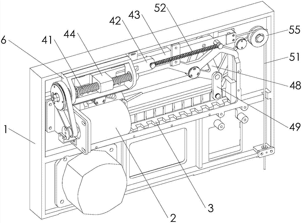
[0037] like figure 1 , figure 2 and image 3 As shown, the paper pressing device of the paper cutter provided by the first embodiment of the present invention includes a frame 1, a motor 2, a pressing plate 3, a transmission mechanism and a pre-pressing mechanism, and the motor drives the pressing plate to rise or fall through the transmission mechanism to realize pressing or The purpose of releasing the paper is realized by the pre-pressing mechanism.

[0038] In this embodiment, the motor 2 is fixed on the frame 1 through the fixing base 7 . The transmission mechanism includes a screw rod 41, a driving rod 42 and a sliding rod 43. The screw rod is controlled by the motor 2, the sliding rod is horizontally installed on the frame 1, the pressure plate 3 is connected to the sliding rod, and the driving rod is arranged on the screw rod and the sliding rod. The motor 2 drives the pressing plate to lower and compress the paper or rise to loosen the paper through the screw rod,...

Embodiment 2

[0057] The difference between the second embodiment of the present invention and the first embodiment is that the traction member adopts a traction chain, one end of the traction chain is fixedly connected to the front end of the sliding rod, and the other end of the traction chain is connected to the pedal.

[0058] Specifically in this embodiment, the traction chain can be an iron chain or a roller chain, and the iron chain is a chain in which a plurality of ring-shaped iron buckles are fastened in sequence. When the traction chain adopts the roller chain, the rollers use the gears that cooperate with the roller chain.

Embodiment 3

[0060] The difference between the third embodiment of the present invention and the first embodiment is that the foot pedal is replaced by a winch, the winch is provided with a handle that is deviated from the axis, and one end of the traction member is fixedly connected to the winch. When the winch is turned, the traction element is forced to move.


PUM


Abstract

The invention discloses a paper pressing device of a paper cutting machine, and belongs to the technical field of electric paper cutting mechanical equipment. The paper pressing device comprises a stand, a pressing plate, a motor and a transmission mechanism, wherein the pressing plate is transversely arranged on the stand and is used for pressing paper; the motor drives the pressing plate to move through the transmission mechanism to press or release the paper; the paper pressing device further comprises a pre-pressing mechanism for driving the pressing plate to move; the pre-pressing mechanism comprises a traction piece connected to the transmission mechanism; and after being stressed, the traction piece drives the pressing plate to move to press the paper through the transmission mechanism. According to the paper pressing device of the paper cutting machine, which is provided by the invention, the pre-pressing mechanism is additionally arranged on the basis of the existing paper pressing device. The pre-pressing mechanism can empty air among pieces of paper, and particularly for relatively smooth paper, the pre-pressing mechanism can enable the adjacent pieces of paper to be closely attached together, so that the influence on the paper cutting effect, which is caused by relative sliding of the paper due to air existing among the paper, during paper cutting is avoided, an error of the paper cutting operation is effectively reduced, and the size accuracy of the paper obtained by cutting is guaranteed.

Description

technical field [0001] The invention relates to the technical field of electric paper cutting machinery and equipment, in particular to a paper pressing device of a paper cutting machine. Background technique [0002] A paper cutter is a cutting machine that is widely used and can be used to cut paper, leather, cardboard and other materials. The paper cutter is mainly composed of a frame, a worktable, a paper pushing mechanism, a paper pressing mechanism, a paper cutting mechanism, etc. During operation, the operator transports the paper from the paper stack to the worktable of the paper cutting machine, and the paper pressing mechanism presses the paper. Tighten the paper, and then, the paper cutting mechanism cuts the paper to achieve the purpose of paper cutting. When the same batch of paper needs to be cut multiple times, the paper pushing mechanism can be used to achieve the purpose of feeding. The paper push action meets the cutting requirements. [0003] The paper ...

Claims


Application Information

Patent Timeline
Patent Type & Authority Applications(China)
IPC IPC(8): B26D7/02B26D7/08
CPCB26D7/015B26D7/025B26D7/08
Inventor 徐登波李坤明杨军坤
Owner CHANGXING FEIXIANG SHEET METAL TECH CO LTD
Learn More