
Wiring platform

A platform and wiring technology, applied in workbenches, manufacturing tools, etc., can solve the problems of rising product processing costs, reducing product production costs, and high requirements for operators and maintenance personnel, and achieves the effect of improving efficiency and strong applicability.

Pending Publication Date: 2017-06-20
QINLONG METAL IND KUNSHAN
View PDF0 Cites 0 Cited by
  • Summary
  • Abstract
  • Description
  • Claims
  • Application Information

AI Technical Summary

Problems solved by technology

In the existing technology, the step of placing materials is mainly done manually, and the output of processing depends on the proficiency of the employees, and can only rely on the operation of old employees. The speed of placing materials for new employees under one year is only 1 / of the speed of old employees. 3. Coupled with the turnover rate of employees and other reasons, skilled employees may not be able to stay with them for a long time, and the salaries of old employees are relatively high, which makes it difficult to choose between processing output and processing cost
In addition, manual operation is also prone to product scrapping caused by personnel negligence, such as placing materials in the mold incorrectly or exceeding the mold, etc.
[0003] The lack of the above-mentioned existing technologies is a problem that needs to be solved urgently in the industry. Some operators have also invented a type of equipment that uses manipulators and automatic control systems to complete material placement. Although this type of equipment liberates manpower, it can also eliminate human-made scrapping factors, but this The cost of manufacturing, purchasing, operating and maintaining such equipment is too high, and the requirements for operators and maintenance personnel are also high, which is unbearable for general processing plants, and even if such equipment is used for material placement, it will cause The increase in product processing costs has not reduced the production cost of products in essence, and has no practical significance for processing plants
Therefore, there is still no feasible technical solution for the swinging problem of such slender rods as iron wires

Method used


Image

  • Wiring platform
  • Wiring platform
  • Wiring platform

Examples


Embodiment 1

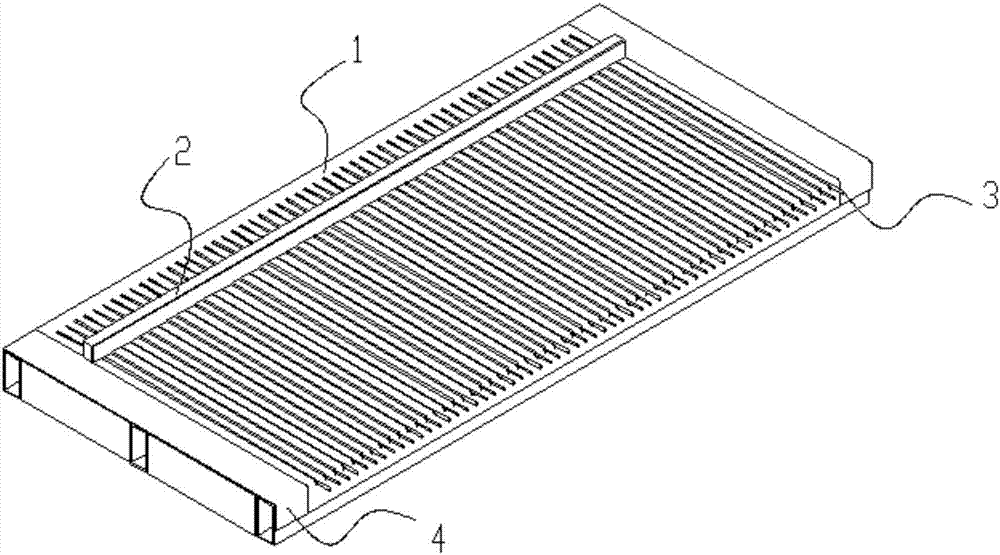
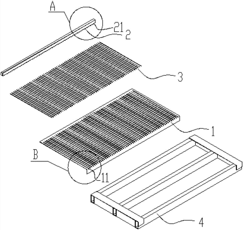
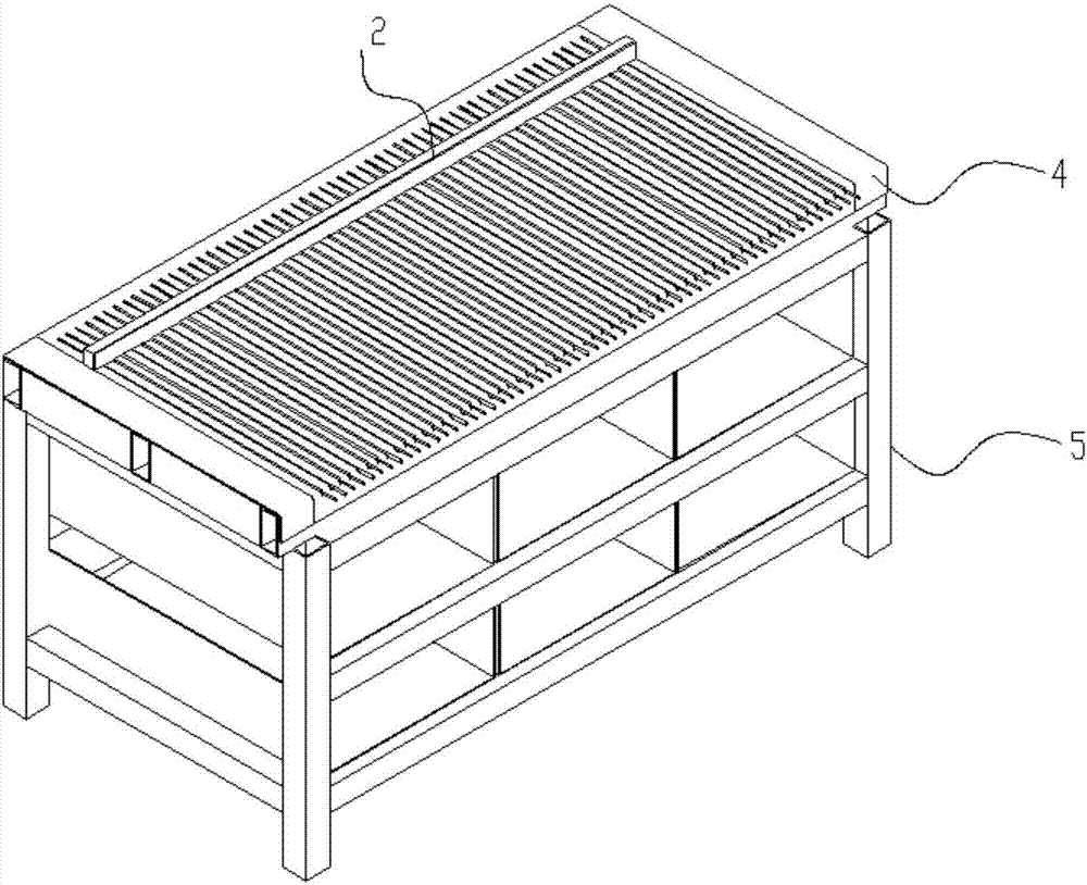
[0036] Embodiment 1: A wiring platform that can independently realize the function of manual swinging, such as Figure 1-3 with Figure 7-8 As shown, it includes a swinging material platform 1 and a width adjustment bar 2. The upper surface of the swinging material platform 1 has a number of wire grooves 11 for placing material rods 3, and each of the wire grooves 11 is along the The width direction of the platform 1 is set, and all the wire slots 11 are arranged at intervals along the length direction of the swing material platform 1 and arranged in parallel, each of the wire slots 11 can only accommodate one material rod 3, so The width adjusting bar 2 is arranged along the length direction of the swing material platform 1 and can be moved and positioned along the width direction of the swing material platform 1, and one end of the material rod 3 after falling into the wire groove 11 stretches out of the Place material platform 1 outside.

[0037]The width adjustment bar 2...

Embodiment 2

[0044] Embodiment 2: an automatic wiring platform, such as Figure 4-6 As shown, the material swing function can be automatically realized, and it has the wiring platform described in Embodiment 1, and is also provided with a pushing mechanism, and the pushing mechanism is connected with a power device, and the pushing mechanism has a 1 above and close to the pusher 6 on the upper surface of the swing platform 1, the power device can drive the pusher 6 along the length direction of the swing platform 1 and close to the upper surface of the swing platform 1 The surface moves.

[0045] Preferably, in this embodiment, the distance between the bottom end of the pushing member 6 and the upper surface of the swing platform 1 is smaller than the diameter of the material rod 3 .

[0046] The pushing mechanism also includes a chute moving bracket 7 and a guide rail 8, the guide rail 8 is arranged along the length direction of the swing material platform 1 and is located on both sides ...


PUM


Abstract

The invention discloses a wiring platform, which can be a manual wiring platform or an automatic wiring platform. The manual wiring platform includes a material swing platform and a width adjustment bar. The groove can only accommodate one material rod, and also includes a bracket platform and a material rack supporting the swing platform. In addition to the manual wiring platform, the automatic routing platform is also provided with a pushing mechanism and a power device connected with the pushing mechanism. The manual wiring platform of the present invention can realize that the operator pushes the material rods on the material swing platform with bare hands or with the help of tools, and the material rods will automatically fall into the wire groove one by one; the automatic wiring platform is based on the manual wiring platform. Automation, the power device drives the pushing mechanism to automatically complete the material placement process on the material placement platform, which can be operated by one person and multiple machines; the above two wiring platforms not only reduce the dependence of placement on manual skills, save manpower, but also have high placement efficiency , The scrap rate is almost zero.

Description

technical field [0001] The invention relates to the technical field of wiring platforms, in particular to a device capable of placing slender rods such as iron wires into the wiring platform for subsequent processing. Background technique [0002] During the processing of metal storage racks (wire mesh steel wire shelves, shoe racks, etc.), metal mesh baskets and other products, it is necessary to place slender rods such as iron wires in the wire slots of the mold one by one to facilitate subsequent Processing, the industry calls it "layout" or "wiring". In the existing technology, the step of placing materials is mainly done manually, and the output of processing depends on the proficiency of the employees, and can only rely on the operation of old employees. The speed of placing materials for new employees under one year is only 1 / of the speed of old employees. 3. Coupled with the turnover rate of employees and other reasons, skilled employees need to be supported for a ...

Claims


Application Information

Patent Timeline
Patent Type & Authority Applications(China)
IPC IPC(8): B25H1/02
CPCB25H1/02
Inventor 蔡忠融
Owner QINLONG METAL IND KUNSHAN
Learn More