
Noodle machine

A noodle machine and noodle cutting technology, applied in the direction of dough mixer, dough forming machinery or equipment, dough sheeting machine/rolling machine/rolling pin, etc., can solve the problem of elongation, destruction of gluten network structure, and no elongation Function and other issues

Active Publication Date: 2017-06-20
湖南楚冠农业科技股份有限公司
View PDF9 Cites 3 Cited by
  • Summary
  • Abstract
  • Description
  • Claims
  • Application Information

AI Technical Summary

Problems solved by technology

[0003] In the industrial production and processing of noodles, mechanized noodle kneading machines are generally used instead. Noodle kneading machines (also known as mixers or kneading machines, etc.) are divided into horizontal and vertical. The base is installed on the central stirring shaft in a spiral shape or inclined to the wall of the barrel at different angles, so that the gluten precipitated from the flour can be mixed evenly with each component, but because the stirring blade is very sensitive to the flour and other components during production and operation. High-speed rotary cutting and agitation destroys the gluten network structure and does not have the effect of kneading, stretching and elongation
As for the vertical dough kneading machine, because the multiple stirring blades on the stirring shaft are not at the same level and are inclined at different angles to the top of the barrel wall, the kneading effect is still similar to that of the horizontal kneading machine. The precipitated gluten is agitated by the high-speed rotary cutting of the stirring blade, which has no elongation effect, and the quality of the network structure of the gluten in the noodles is also not fully displayed.

Method used


Image

  • Noodle machine
  • Noodle machine

Examples


Embodiment Construction

[0016] The present invention will be described in further detail below by means of specific embodiments:

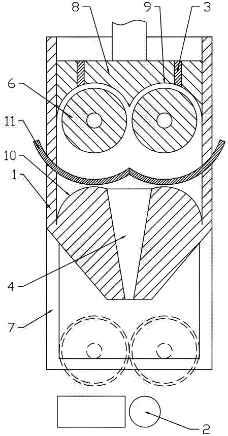
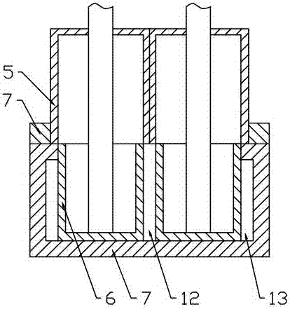
[0017] The reference signs in the accompanying drawings of the description include: material barrel 1, surface cutting mechanism 2, nozzle 3, discharge port 4, roll holder 5, surface roller 6, chute 7, piston 8, wedge-shaped surface 9, convex surface 10, Arc plate 11, scoop surface gap 12, extrusion gap 13.

[0018] The embodiment noodle machine is basically as attached figure 1 Shown: It includes a material barrel 1 for kneading, a rolling mechanism and a noodle cutting mechanism 2. There is a nozzle 3 inside the material barrel 1, and a discharge port 4 is provided at the bottom of the material barrel 1. The calendering mechanism is installed under the material barrel 1, and the surface is cut. The mechanism 2 is installed below the calendering mechanism. The cross section of the material barrel 1 is rectangular. Two roller holders 5 are installed on the side wall of t...


PUM


Abstract

The present invention relates to the fields of mechanical devices for processing dough and discloses a noodle machine. The noodle machine comprises a material bucket used for dough kneading, a rolling mechanism and a dough piece cutting mechanism. A material outlet is arranged at the bottom of the material bucket, the rolling mechanism is arranged at the lower part of the material bucket, the dough piece cutting mechanism is arranged under the rolling mechanism, the cross section of the material bucket is rectangular, two roller containing devices are arranged at the side wall of the material bucket, the inside of the roller containing devices is hollow, the roller containing devices communicates with the material bucket, a dough kneading roller is in slide connection within each of the roller containing devices, a driving device for driving the dough kneading rollers to rotate is connected to the end faces of the dough kneading rollers, a material scooping gap of 5-10 mm is formed between the two dough kneading rollers, and a squeezing gap of 3-8 mm is formed between each dough kneading roller and the side wall of the material bucket; and a piston is slidably connected within the material bucket, one side, facing towards the material outlet, of the piston is wedge-shaped, and a tip end of the wedge-shape faces toward the material scooping gap. The present invention aims to provide the noodle machine. The noodle machine mechanically produces the noodles, forms regular gluten structures in the interior of the dough in the dough kneading processes, and ensures the mouthfeel of the finished products of the noodles.

Description

technical field [0001] The invention relates to the field of machinery and equipment for processing dough. Background technique [0002] Kneading noodles is an important process in noodle processing. It is to knead and press flour, water and other auxiliary materials repeatedly to make the ingredients of raw materials evenly mixed. The gluten in the flour is fully analyzed and mixed evenly with other ingredients, and then extended It is elongated into a network structure, so the finished noodles are tough and not easy to break. They are not easy to paste when cooked and cooked, and the taste is also soft and refreshing. [0003] In the industrialized production and processing of noodles, mechanized noodle kneading machines are generally used instead. Noodle kneading machines (also known as mixers or kneading machines, etc.) are divided into horizontal and vertical. The base is installed on the central stirring shaft in a spiral shape or inclined to the wall of the barrel at...

Claims


Application Information

Patent Timeline
IPC IPC(8): A21C11/10A21C1/08A21C1/14A21C3/02
CPCA21C1/083A21C1/1435A21C3/024A21C11/10
Inventor 岳光羽
Owner 湖南楚冠农业科技股份有限公司
Learn More