
Electric energy converting-switching system and method and application thereof

A technology of electric energy conversion and switching system, which is applied in the direction of single AC network with different frequencies, AC network with the same frequency of different sources, single network parallel feeding arrangement, etc., which can solve the problems of reducing motor life, system flexibility constraints, Issues with greater impact

Pending Publication Date: 2017-06-13
上海申能电力科技有限公司
View PDF0 Cites 2 Cited by
  • Summary
  • Abstract
  • Description
  • Claims
  • Application Information

AI Technical Summary

Problems solved by technology

[0003] However, the existing centralized frequency conversion power supply technology also has certain shortcomings: on the one hand, throttling loss occurs
In order to match the power imbalance between the two, and to meet the power and frequency required by the electric motor of the plant auxiliary machine under the working condition of the main steam turbine generator set, it is necessary to rely on adjusting the opening of the steam inlet regulating valve of the small steam turbine. Help to adjust the operating pressure of the small steam turbine to achieve the purpose of adjusting the speed and output power of the small steam turbine, resulting in throttling loss
[0004] In the second case, due to the design margin of the extraction steam source of the small steam turbine itself, or the adjustment of the operation mode, throttling loss will also occur
In the above cases, throttling loss will occur
[0005] On the other hand, the existing centralized frequency conversion power supply technology will restrict the flexibility of the system's operation mode, and the start-up and switching of the motors of the plant's auxiliary machines will be restricted.
It is reflected in: Generally, the motor of the plant auxiliary machine is directly started under the power frequency condition. In this starting mode, the starting current is relatively large, generally up to 4-7 times the rated current, which will reduce the life of the motor and affect the Other devices on the same bus have a greater impact, and the requirements for system capacity are relatively high
The motor of the factory auxiliary machine cannot complete the switching under the condition of frequency conversion

Method used


Image

  • Electric energy converting-switching system and method and application thereof
  • Electric energy converting-switching system and method and application thereof
  • Electric energy converting-switching system and method and application thereof

Examples


specific Embodiment approach 1

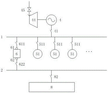
[0143] Such as figure 1 As shown, a specific embodiment of the electric energy conversion and switching system of the present invention, it includes No. 1 factory bus 1, No. 2 factory bus 2, variable frequency generator 4, and drive variable frequency generator 4 to send out alternating current with variable frequency The small steam turbine 44 of the small steam turbine, the steam inlet regulating valve 45 for controlling the steam inlet volume of the small steam turbine 44, the power frequency plant power system 8, the motors 51 of multiple No. 51 plant auxiliary machines, and the frequency and / or the frequency of at least one connection end can be adjusted. voltage, and control the flow of electric energy between plant buses of different frequencies, or a power converter 6 that can control electric energy at different frequencies and control the flow of electric energy between plant buses of the same frequency. The power converter 6 includes No. 61 connection end 61 and No...

specific Embodiment approach 2

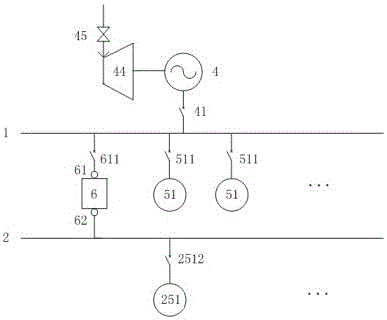
[0158] Such as figure 2 As shown, another specific embodiment of a power conversion and switching system of the present invention, it includes No. 1 factory bus 1, No. 2 factory bus 2, variable frequency generator 4, and the output frequency of the driving variable frequency generator 4 can be changed The small steam turbine 44 of alternating current, the steam inlet regulating valve 45 controlling the steam inlet volume of the small steam turbine 44, the motor 51 of multiple No. 51 plant auxiliary machines, the motor 251 of No. 251 plant auxiliary machines, and the motor 251 that can adjust at least one connection end Frequency and / or voltage, and control the flow of electric energy between plant buses of different frequencies, or, a power converter 6 that can control electric energy at different frequencies and control the flow of electric energy between plant buses of the same frequency, electric energy The converter 6 includes a No. 61 connection terminal 61, a No. 62 con...

specific Embodiment approach 3

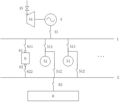
[0162] Such as image 3 As shown, another specific embodiment of a power conversion and switching system of the present invention, it includes No. 1 factory bus 1, No. 2 factory bus 2, variable frequency generator 4, and the output frequency of the driving variable frequency generator 4 can be changed The small steam turbine 44 of alternating current, the steam inlet regulating valve 45 controlling the steam inlet volume of the small steam turbine 44, the power frequency plant power system 8, the motor 51 of multiple No. 51 factory auxiliary machines, and the frequency and frequency of at least one connection end can be adjusted / or voltage, and control the flow of electric energy between plant buses of different frequencies, or a power converter 6 that can control electric energy at different frequencies and control the flow of electric energy between plant buses of the same frequency, power converter 6 includes No. 61 connecting end 61 and No. 62 connecting end 62 and so on....


PUM


Abstract

The invention discloses an electric energy converting-switching system and method applied to a thermal power plant. The frequency and / or voltage of at least one connection end can be adjusted through an electric energy transducer, and electric energy is controlled to flow among plant buses of different frequencies, or the electric energy can be controlled at different frequencies and can be controlled to flow among the plant buses of different frequencies, so that the throttling loss is reduced and even eliminated, the performance of a variable-frequency generating set is brought into full play, and the overall system efficiency is increased, thereby lowering the energy consumption and creating a greater economic benefit; meanwhile, a method of starting and switching through a motor of an auxiliary machine for a plant is improved, so that the flexibility of the overall running manner of the system is improved.

Description

technical field [0001] The present invention relates to a switching system and method for electrical energy conversion and plant auxiliary motors applied in thermal power plants, which can control the flow of electric energy between plant buses of different frequencies in thermal power plants, or both can Controlling electric energy at different frequencies can also control the flow of electric energy between plant buses of the same frequency, and can help start and / or switch electric motors of plant auxiliary machines in thermal power plants. Background technique [0002] Energy conservation and emission reduction are not only the external requirements put forward by the state and society for thermal power plants, but also the internal requirements for thermal power plants to reduce costs, increase profits, and fulfill social responsibilities. Therefore, thermal power plants are actively tapping internal potentials and carrying out energy-saving transformation , innovative ...

Claims


Application Information

Patent Timeline
IPC IPC(8): H02J3/02H02J3/06H02J3/46
CPCH02J3/02H02J3/06H02J3/46
Inventor 冯伟忠
Owner 上海申能电力科技有限公司
Learn More