Amplitude type fractal spiral wave zone plate

A helical wave, amplitude type technology, applied in the field of diffractive optics to achieve the effect of enhancing resolution

Inactive Publication Date: 2017-06-13
ZHENGZHOU UNIV
View PDF3 Cites 9 Cited by
  • Summary
  • Abstract
  • Description
  • Claims
  • Application Information

AI Technical Summary

Problems solved by technology

A telescope can be used to compress a beam with multiple vortices for 3D optical trapping, but this is only available in the visible region

Method used


Image

  • Amplitude type fractal spiral wave zone plate
  • Amplitude type fractal spiral wave zone plate
  • Amplitude type fractal spiral wave zone plate

Examples


Embodiment Construction

[0032] The application principle of the present invention will be further described below in conjunction with the accompanying drawings and specific embodiments. It should be understood that the specific embodiments described here are only used to explain the present invention, not to limit the present invention.

[0033] see Figure 1-Figure 7 :

[0034] This embodiment discloses an amplitude type fractal spiral zone plate suitable for soft X-ray transmission, refer to figure 1 with figure 2 ; figure 1 Shown is the 54 periods of the present invention, the schematic diagram of the structure of the amplitude type fractal helical zone plate of l=1, the helical annulus filled in white in the figure is the translucent part, and the black area is the opaque part; figure 2 For the present invention in (r 2 , θ) Schematic diagram of the structure in the coordinate system.

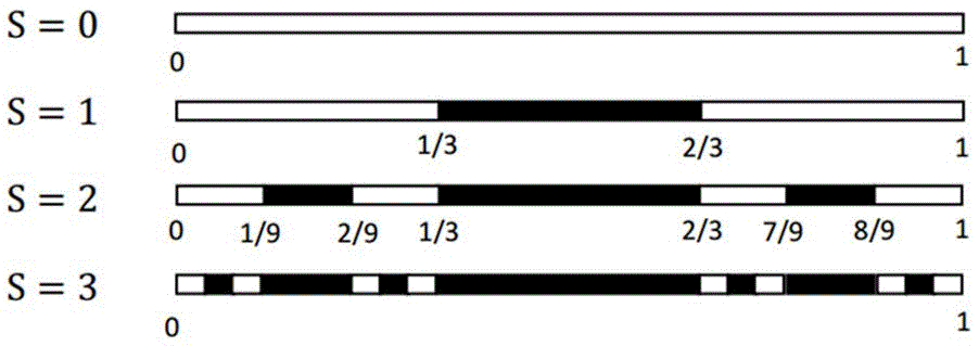
[0035] For the cantor set of N=2, S=3, we have 3 a 1 = 0, 3 a i Indicates the starting position...


PUM


Abstract

The invention discloses an amplitude type fractal spiral wave zone plate. According to the amplitude type fractal spiral wave zone plate, a series of light permeable spiral annular zones are obtained by applying cantor set fractal to amplitude angles of the spiral wave zone plate, and the coordinates of the light permeable spiral annular zones meet the formulas shown in the description. On the basis of the spiral wave zone plates, the self-similarity of the fractal is combined, and the annular zones are obtained by applying the cantor set fractal to the amplitude angles. Equivalently, a series of transparent half-wave zones and non-transparent half-wave zones with self-similarity are picked out from the directions of the amplitude angles. Compared with common spiral wave zone plate of the same numerical aperture, a series of zonal turbulent structures can be obtained. By adjusting N and S, the fractal period can be controlled, and different fractal spiral wave zone plates can be obtained. In the research fields of extreme ultraviolet lithography, tiny electric power systems and the like, the amplitude type fractal spiral wave zone plate has the wide application prospect, and the application range of visual light, extreme ultraviolet, X ray and other multiple wave band three-dimensional trapped particles is enlarged.

Description

technical field [0001] The invention relates to the field of diffractive optics, in particular to an amplitude type fractal spiral zone plate. Background technique [0002] Due to the rapid development of singularity optics, optical vortices have been widely used in particle manipulation, such as optical tweezers and optical wrenches. The phase singularity of the optical vortex allows trapped particles to be less damaged and better isolated than those trapped by a strongly focused beam. Furthermore, optical traps consisting of focused beams with multiple traps have been widely used to trap various types of particles in three-dimensional space. In recent years, X-ray vortices have attracted increasing attention in the selective control of particles due to their unique properties. For example, when using a vortex beam as an optical wrench, the angular momentum is transferred to the particle through the absorption of the photon by the particle to achieve rotation and other ma...

Claims


Application Information

Patent Timeline
Patent Type & Authority Applications(China)
IPC IPC(8): G02B5/18
CPCG02B5/1876
Inventor 臧华平郑程龙吉子雯
Owner ZHENGZHOU UNIV
Why Eureka
Try Eureka