Near-field antenna test system based on frequency division and test system thereof
A test system and near-field antenna technology, which is applied to antenna radiation patterns, measuring devices, electromagnetic field characteristics, etc., can solve the problems of long test time for large-scale phased array antennas, improve test speed and test efficiency, and save switching time Effect
- Summary
- Abstract
- Description
- Claims
- Application Information
AI Technical Summary
Problems solved by technology
Method used
Image

Examples
Embodiment 1
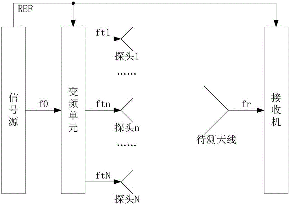
[0036] see figure 1 , when the antenna to be tested is a receiving antenna, Embodiment 1 of the frequency division-based near-field antenna testing system of the present application includes:
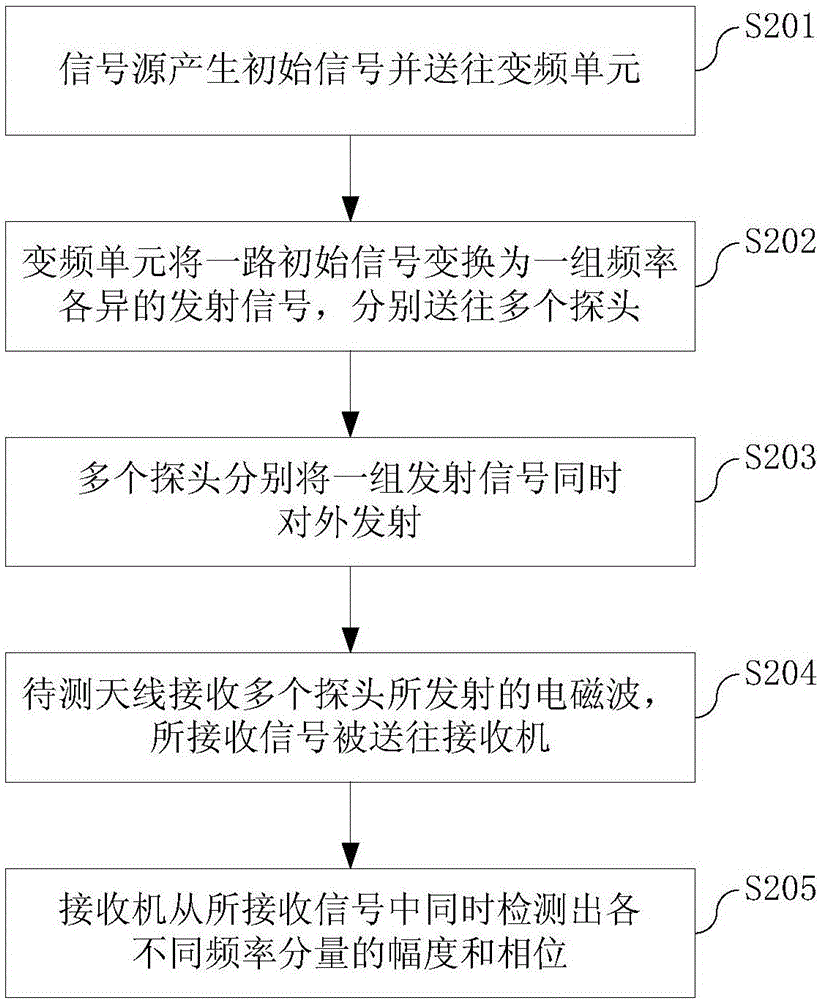
[0037] ——The signal source is connected to the frequency conversion unit through a cable. The signal source is used to generate the initial signal f0 and send it to the frequency conversion unit. The initial signal f0 is, for example, generated by a crystal oscillator (crystal oscillator) and optionally obtained through frequency conversion. The initial signal f0 is used as a test frequency of the entire near-field antenna test system.
[0038] The signal source also sends its own clock signal as a reference signal REF to each component of the entire near-field antenna test system, so as to provide a unified time reference for the entire near-field antenna test system. The reference signal REF is, for example, 10 MHz.
[0039] ——Frequency conversion unit, connect each probe through c...
Embodiment 2
[0072] Embodiment 2 can also adopt the same frequency traversal scanning as Embodiment 1, probes covering the entire near-field scanning surface, conversion of near-field test parameters and far-field test parameters, and other additional solutions.
[0073] see Image 6 , which is the third embodiment of the frequency division-based near-field antenna testing system of the present application when the antenna to be tested is a receiving antenna. Compared with the first embodiment, the third embodiment replaces the single signal source and the frequency conversion unit in the first embodiment with multiple signal sources.
[0074] The multiple signal sources are connected to each probe through a cable. The multiple signal sources are used to generate a set of coherent transmission signals ft1-ftN. Coherence means that the signals generated by each signal source have a definite phase relationship. The frequencies of this group of transmitted signals ft1~ftN are different, bu...
Embodiment 3
[0080] Embodiment 3 may also adopt the same additional schemes as in Embodiment 1, such as frequency traversal scanning, probe covering the entire near-field scanning surface, conversion of near-field test parameters and far-field test parameters, and the like.
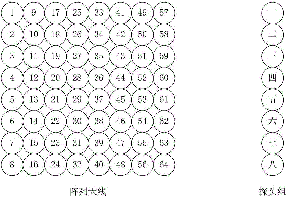
[0081] Compared with the existing single-probe phased array near-field antenna test system, the near-field antenna test system of the present application uses multiple probes, which can significantly improve the antenna test speed and test efficiency, and shorten the test time. Compared with the existing multi-probe phased array near-field antenna test system, this application replaces the switch switching mode with frequency division (frequency division), because the switch switching time is omitted, and multiple probes can be transmitted together by the waiting The test antenna is simultaneously received and detected and analyzed by the single channel of the receiver, which further improves the test speed and test ef...
PUM
 Abstract
Description
Claims
Application Information
 - R&D
- Intellectual Property
- Life Sciences
- Materials
- Tech Scout
- Unparalleled Data Quality
- Higher Quality Content
- 60% Fewer Hallucinations
Browse by: Latest US Patents, China's latest patents, Technical Efficacy Thesaurus, Application Domain, Technology Topic, Popular Technical Reports.
© 2025 PatSnap. All rights reserved.Legal|Privacy policy|Modern Slavery Act Transparency Statement|Sitemap|About US| Contact US: help@patsnap.com