Automobile, ECU of automobile, suspension system, spring damping device and control system

A vibration damping device and control system technology, applied in control systems, automobiles and their ECUs, spring damping devices, and suspension systems, can solve the problems of increased cost and layout space, limited vibration damping performance of shock absorbers, etc. Problems, to achieve the effect of increasing product utilization, increasing flowable space, and simple layout

Active Publication Date: 2017-06-13
SAIC MOTOR
View PDF6 Cites 4 Cited by
  • Summary
  • Abstract
  • Description
  • Claims
  • Application Information

AI Technical Summary

Problems solved by technology

[0005] The problem solved by the present invention is that in the spring damper in the existing suspension system, the damping performance of the damper is limited by its own size and the flowable space of the internal fluid, if better damping performance is to be obtained , it is necessary to increase the size of the shock absorber itself to increase the flowable space of the fluid, which will undoubtedly increase the cost and the difficulty of layout space

Method used


Image

  • Automobile, ECU of automobile, suspension system, spring damping device and control system
  • Automobile, ECU of automobile, suspension system, spring damping device and control system
  • Automobile, ECU of automobile, suspension system, spring damping device and control system

Examples


Embodiment Construction

[0057] In order to make the above objects, features and advantages of the present invention more comprehensible, specific embodiments of the present invention will be described in detail below in conjunction with the accompanying drawings.

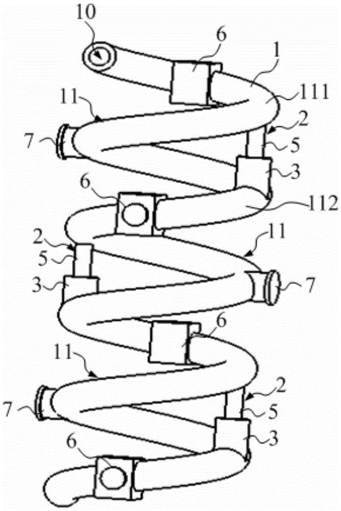
[0058] refer to Figure 1 ~ Figure 3 , this embodiment provides a spring damping device, including: a coil spring 1 and a shock absorber 2;

[0059] A spring cavity 10 extending to both ends of the spring wire along the helical direction is formed in the spring wire of the coil spring 1;

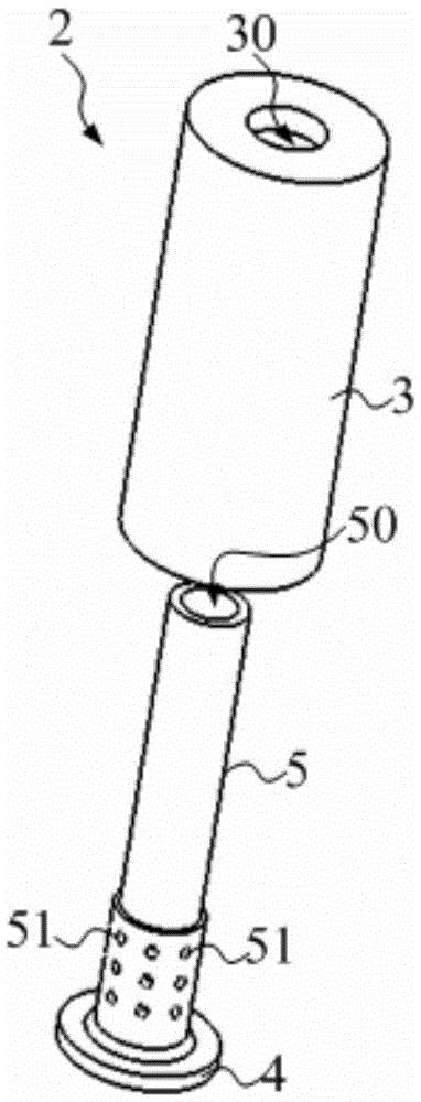
[0060] The shock absorber 2 includes a working cylinder 3 with a piston chamber 30, a piston 4 slidably located in the piston chamber 30, and a guide rod 5 connected to the piston 4 and having a guide rod chamber 50. The piston chamber 30 is divided into a second section by the piston 4. A cavity 31 and a second cavity 32, the guide rod 5 is connected to one end of the piston 4 located in the first cavity 31 and extends out of the first cavity 31, the g...


PUM


Abstract

The invention provides an automobile, an ECU of the automobile, a suspension system, a spring damping device and a control system. The spring damping device comprises a spiral spring and the damper. A spring inner cavity extending to the two ends of the spring line in the spiral direction is formed in the spring line of the spiral spring. The damper comprises a working cylinder provided with a piston cavity, a piston slidably located in the piston cavity, and a guide rod connected with the piston and provided with a guide rod cavity. The piston cavity is divided into a first cavity and a second cavity by the piston, the first cavity is defined by the piston and the guide rod, and the guide rod cavity or the second cavity communicates with the first cavity. The spring inner cavity comprises at least one working section in the spiral section. The damper connected to the spring line is arranged outside the working section. The length direction of the guide rod is parallel to the axial direction of the spiral spring. The guide rod cavity and the second cavity communicate with the working section. Flowing fluid is contained in the working section. According to the technical scheme, the spring damping device is small in occupied space and has good buffering and damping performance, and arrangement difficulty is lowered.

Description

technical field [0001] The invention relates to the technical field of automobiles, in particular to an automobile and its ECU, suspension system, spring damping device and control system. Background technique [0002] Suspension system is a general term for all force-transmitting connection devices between the frame of a car and the axle or wheels. Or the impact force of the car body, and attenuate the vibration caused by it, so as to ensure the smooth running of the car. The proper function of the suspension system is to support the body and improve the ride. [0003] The suspension system includes a spring shock absorber, and the spring shock absorber includes a coil spring and a shock absorber installed in the coil spring, wherein the two ends of the coil spring and the shock absorber are respectively connected to the wheel and the vehicle frame, wherein, When passing through uneven roads, the coil spring can absorb the vibration from the road, but the coil spring itse...

Claims


Application Information

Patent Timeline
IPC IPC(8): F16F9/18F16F9/46F16F13/00B60G17/015
CPCF16F9/18F16F9/466F16F13/007B60G17/0152F16F9/182F16F9/19
Inventor 李根易斌沈伟芦勇王东李剑骆建军江洲李思明王威张宏王玉洁赵雪利
Owner SAIC MOTOR
Why Eureka
Try Eureka