
A cp type single screw pump

A single-screw pump and screw technology, which is applied in the direction of pumps, pump components, pump control, etc., can solve the problems of unable to realize the delivery of fluid medium, trapped liquid, etc., achieve the effect of simple structure, small pulsation of instantaneous flow rate, and reduce manufacturing difficulty

Active Publication Date: 2018-12-07
NORTHWEST A & F UNIV
View PDF2 Cites 0 Cited by
  • Summary
  • Abstract
  • Description
  • Claims
  • Application Information

AI Technical Summary

Problems solved by technology

When rotating forward, if the triangular orifice on the CP single-screw compressor is still used as the discharge orifice of the CP single-screw pump, when the screw groove is closed, there is still a long section between the working chamber and the orifice in the circumferential direction of the cylinder. Due to the incompressibility of the liquid, the liquid trapped in the working chamber cannot be discharged, and the phenomenon of trapped liquid will occur, and the function of conveying the fluid medium cannot be realized
When reversing, if the triangular orifice on the CP single-screw compressor is still used as the suction orifice of the CP single-screw pump, when the screw groove turns over the triangular orifice, no fluid medium will enter the working chamber. However, the direction of movement of the star gear teeth further increases the working chamber. Since the liquid cannot expand, the phenomenon of trapped liquid will also occur, and the function of conveying fluid medium cannot be realized.

Method used


Image

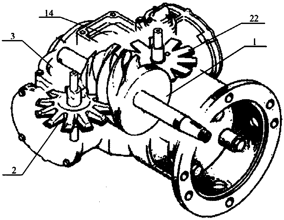
  • A cp type single screw pump
  • A cp type single screw pump
  • A cp type single screw pump

Examples


Embodiment 1

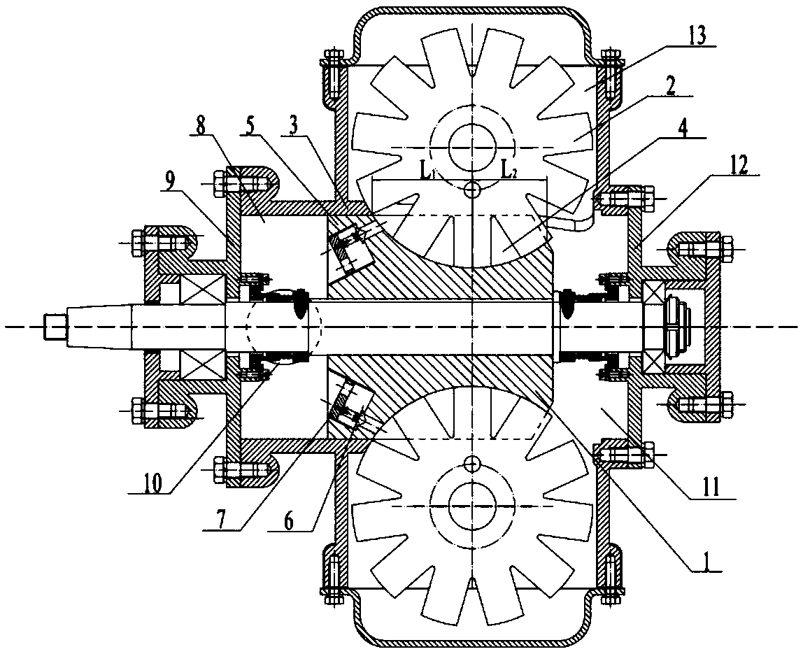
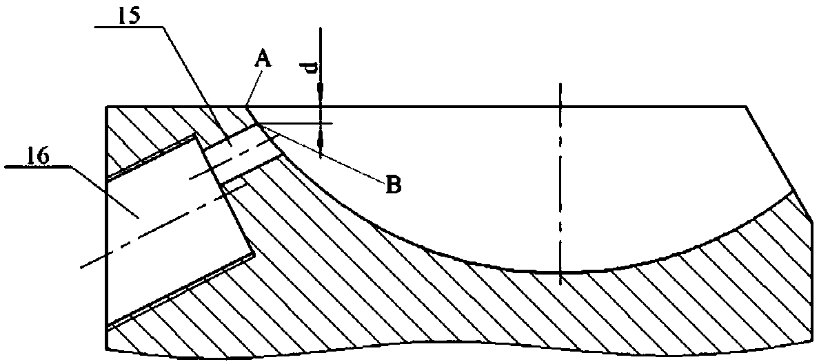
[0047] Embodiment 1: The pump rotates forward and the installed valve assembly is a ball valve or a cone valve. see Figure 5 , the valve plate 17 is provided with a second through hole 21, which is an eccentric hole. The lift limiter 19 of the valve assembly 7 is connected with the valve plate 17 through the thread at its tail. The spring 18 root is welded on the valve plate 17, and the valve core (ball or cone) 20 is welded on the spring 18 top. The center lines of lift limiter 19, spring 18 and spool 20 should coincide. It is required that the eccentricity of the centerline of the lift limiter 19 to the centerline of the valve plate 17 is the same as the eccentricity of the centerline of the first round hole 15 to the centerline of the second round hole 16 . The valve plate 17 on which the valve assembly is installed is screwed into the second circular hole 16, and the centerline of the lift limiter 19 is required to coincide with the centerline of the first circular hol...

Embodiment 2

[0052] Embodiment 2: The pump is reversed, and the installed valve assembly is a ball valve or a cone valve. see Image 6 , The valve plate 17 is provided with a second through hole 21, which is an eccentric hole. The lift limiter of the valve assembly 7 is physically connected with the screw behind the interface with the stepped first through hole 6 through the screw thread at the tail. The root of the spring 18 is welded on the interface of the stepped first through hole 6 , and the valve core 20 (ball or cone) is welded on the top of the spring 18 . The center lines of lift limiter 19, spring 18 and spool 20 should coincide. It is required that the eccentricity of the centerline of the lift limiter 19 to the centerline of the second circular hole 16 is the same as the eccentricity of the centerline of the second through hole 21 on the valve plate 17 to the centerline of the valve plate 17 . When the valve plate 17 is screwed into the first circular hole 15, the center li...

Embodiment 3

[0056] Embodiment 3: The pump rotates forward and the installed valve assembly is a strip valve. see Figure 7 , The valve assembly is composed of valve plate 17, valve plate 22 and lift limiter 23. A second through hole 21 is provided on the valve plate along a direction parallel to the centerline of the valve plate, and the second through hole 21 is an eccentric hole. The valve sheet 22 is a strip-shaped metal sheet with elasticity. The lift limiter 23 is a metal sheet with high rigidity. The lift limiter 23 and the root of the valve plate 22 are fastened on the valve plate 17 by screws 24 . The valve assembly 7 is screwed into the second round hole 16 and locked, and the valve plate 22 and the lift limiter 23 are located on the side close to the first chamber 8 . The rigidity of the used valve plate 22 should not only ensure that the cracking pressure δP is not too large to avoid additional energy loss, but also ensure that the valve plate 22 can quickly adhere to the o...


PUM


Abstract

The invention discloses a CP type single-screw pump, which is applied to single-phase liquid conveyance or gas-liquid two-phase mixed conveyance. Particularly, when a pump performs positive rotation, and the gas-liquid two-phase flow is conveyed in a mixed way, the inner compression on gas-phase media can be automatically realized. The CP type single-screw pump is characterized in that a first through hole is formed at the back part of a screw rod and between a region with the screw groove depth approaching to 0 and the back part end surface of the screw rod; a valve assembly used for controlling the fluid suck-in or discharge-out process is arranged in the first through hole; a through hole with the completely identical position and shape as the first through hole is formed in a way of being corresponding to each screw groove; a valve assembly identical to the valve assembly is arranged in each through hole. The invention provides a key technology for developing CP type single-screw machinery to a pump field. The CP type single-screw pump has the advantages that the structure is simple; the lift head is high; the efficiency is high; the self suction capability is high, and the like. The CP type single-screw pump can be used in the fields of urban water supply, irrigation, oil-gas mixed conveyance and the like.

Description

Technical field: [0001] The invention relates to a pump, in particular to a CP type single screw pump. Background technique: [0002] The screw pump is a rotary pump that relies on the volume change and movement of the meshing space formed by the pump body and the screw to transport or pressurize the fluid medium. The screw pump has the characteristics of small size, high efficiency and high lift, and has self-priming function. It is a constant flow pump, and the flow rate is proportional to the speed. Screw pumps include single screw pumps, twin screw pumps, triple screw pumps, etc. A single screw pump usually refers to a positive displacement pump in which a single screw rotates in an internal thread groove of the pump body to drive a fluid medium. In the existing literature (patent number: WO82 / 03428), the CP single-screw machine widely used in the field of compressors is applied to the field of pumps, and a CP-type single-screw pump is proposed. Conveying fluid media....

Claims


Application Information

Patent Timeline
Patent Type & Authority Patents(China)
IPC IPC(8): F04C2/107F04C15/06F04C13/00F04C14/26
CPCF04C2/107F04C13/001F04C14/26F04C15/064F04C2210/24
Inventor 李挺陈帝伊江伟张宁陈实冯全科
Owner NORTHWEST A & F UNIV
Learn More