Floor bracket

A floor and bottom plate technology is applied in the field of devices supporting the floor, and can solve the problems of inconvenient readjustment and the like

Inactive Publication Date: 2017-06-13
哈尔滨旺得福科技发展有限公司
View PDF1 Cites 0 Cited by
  • Summary
  • Abstract
  • Description
  • Claims
  • Application Information

AI Technical Summary

Problems solved by technology

The problem with this product is that it cannot be easily readjusted during floor installation

Method used


Image

  • Floor bracket
  • Floor bracket

Examples


Embodiment Construction

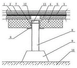
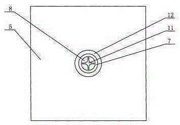
[0011] Depend on figure 1 The cutaway view of the floor bracket shown and figure 2 It can be known from the top view of the floor support that the floor support includes a base (9), a screw (8), a support portion (6) and a floor support seat (5). Wherein the upper part of the screw rod (8) is provided with a supporting part (6), the lower end of the screw rod (8) is placed in the cavity of the base (9), and the top of the screw rod is provided with a sinking groove (11) for tightening. A counterbore (12) is provided on the upper plane of the floor support seat (5), a floor support seat (5) is provided above the support portion (6), the through hole (13) in the middle of the floor support seat (5) and the support portion reinforcement nut (7) Fitting, the height of the support portion reinforcement nut (7) is flush with the lower edge of the counterbore (12), and the through hole (13) is located in the middle of the counterbore (12). The support part (6) is provided with a r...


PUM


Abstract

The invention relates to a floor bracket. The bracket includes a base, a screw, a support part and a base plate support seat. The upper part of the screw rod is provided with a support part, the lower part is provided with a base, the top of the screw rod is provided with a sinker, and the support part is provided with a base plate support seat. The invention can conveniently adjust the height of the floor support, reasonably control the height of the floor, and facilitate construction and arrangement of pipelines. The invention can be applied to interior decoration.

Description

[0001] Technical field: [0002] The invention relates to a device for supporting a floor, in particular to a floor support. Background technique [0003] In the interior decoration process, there are generally many pipelines that need to be laid under the floor. As the actual situation changes, the optimal height of the floor will also change accordingly. Therefore, people in related industries have adopted many new technologies for innovation. Wherein the publication number is CN2219346, the name is the invention patent of access floor bracket, discloses a kind of access floor bracket, this access floor bracket is made up of upper support, lower seat, screw rod, adjusting nut, and adjusting nut is positioned at the upper part and the lower part of screw rod, uses For height adjustment, the lower part of the screw rod is a bowl-shaped lower seat supported by three-point protrusions, and the upper part is a steel stamping part with triangular columns on both sides and a recta...

Claims


Application Information

Patent Timeline
Patent Type & Authority Applications(China)
IPC IPC(8): E04F15/024
Inventor 不公告发明人
Owner 哈尔滨旺得福科技发展有限公司
Why Eureka
Try Eureka