
Active pay-off tension control device and wire winding method thereof

A technology of pay-off tension and control device, which is applied in the direction of transportation and packaging, delivery of filamentous materials, thin material processing, etc., can solve the problems of wire stretching deformation, increased defective rate, and substandard product quality. Improved production efficiency, high production efficiency, and simple assembly

Inactive Publication Date: 2017-06-13
CHINA JILIANG UNIV
View PDF0 Cites 7 Cited by
  • Summary
  • Abstract
  • Description
  • Claims
  • Application Information

AI Technical Summary

Problems solved by technology

During the pay-off process, if the tension is too high, the wire will be stretched and deformed or even broken, causing the entire production process to be interrupted and affecting production efficiency; if the tension is too small, it will cause the wire to loop back, causing low-frequency vibration of the wire, resulting in improper winding. Uniformity, which affects the quality and production efficiency of the wire
Due to the change of tension, the line speed of the wire will fluctuate, and the degree of tightness of the wire on the wire drum will also change accordingly, resulting in substandard product quality and increased defective rate

Method used


Image

  • Active pay-off tension control device and wire winding method thereof
  • Active pay-off tension control device and wire winding method thereof
  • Active pay-off tension control device and wire winding method thereof

Examples


Embodiment Construction

[0023] Below in conjunction with accompanying drawing, the present invention is described in further detail:

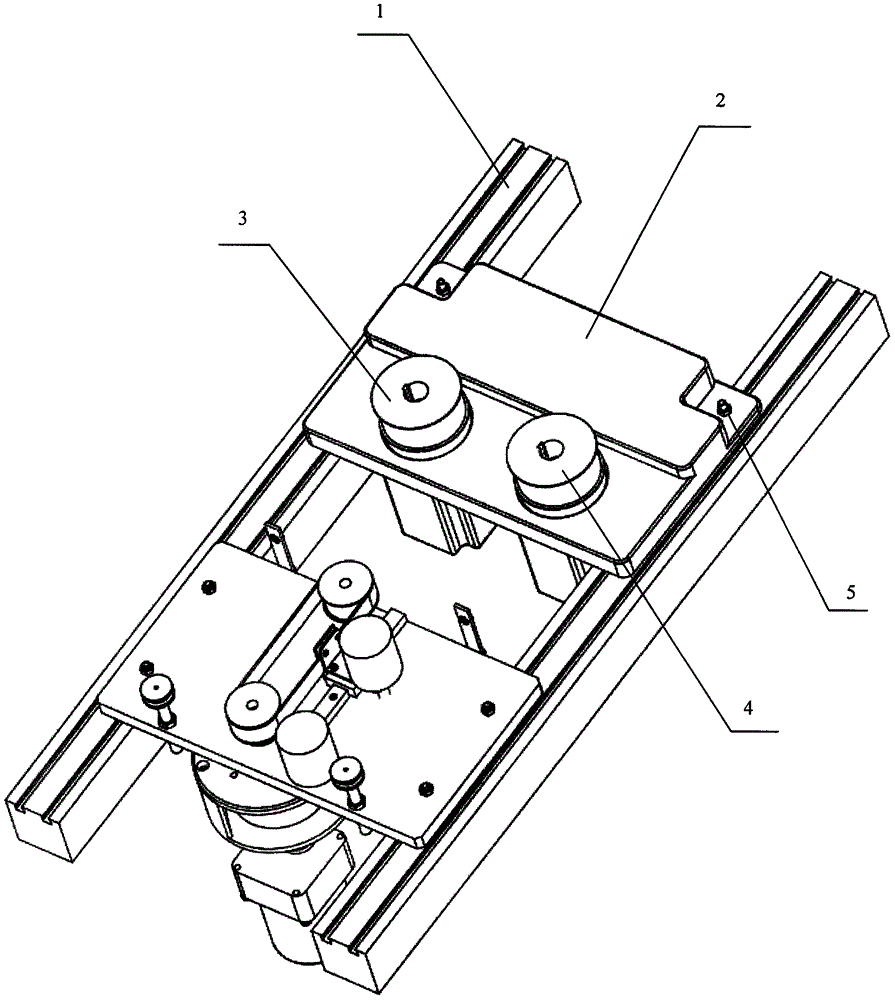
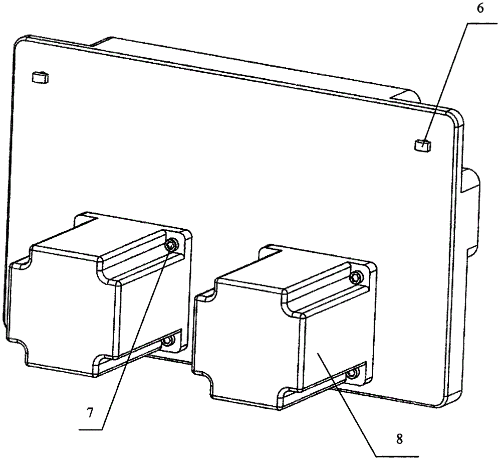
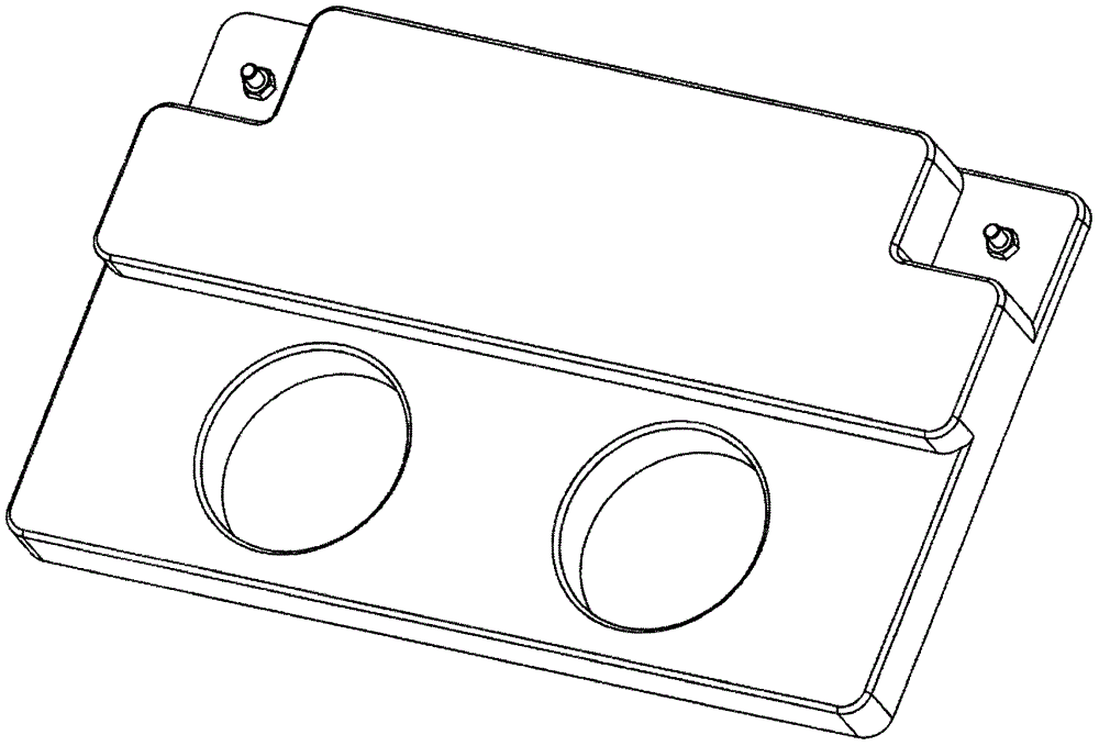
[0024] refer to Figure 1 to Figure 19 , an active pay-off tension control device provided by the present invention, such as figure 1 shown, including: figure 2 and image 3 motor board shown, Figure 4 bracket shown, Figure 5 Pay-off barrel shown, Image 6 Take-up barrel shown, Figure 7 and Figure 8 The tension feedback device shown, Figure 9 base plate shown, Figure 10 ceramic eye mounting plate shown, Figure 11 guide wheel shown, Figure 12 It is the fixed seat of the synchronous pulley shaft, Figure 13 , 14 and the floating structure shown in 15, Figure 16 mobile plate shown, Figure 17 fixed plate shown, Figure 18 floating roller shown, Figure 19 Fixed roller shown.

[0025] During use, the motor board 2 is fixed on the fixed frame 1 with bolts 6 and nuts 5 of the T-shaped slot. Similarly, the bottom plate 9 is fixed on the fixed frame...


PUM


Abstract

The invention provides an active pay-off tension control device and a winding method thereof. Including: bottom plate, ceramic eye mounting plate, synchronous belt and synchronous pulley, floating roller and fixed roller, two guide wheels, countersunk screws, nuts, moving plate, slider, linear guide rail, fixed plate, damper and its housing , and the speed motor. The guide wheel, fixed roller and synchronous pulley are fixed on the bottom plate by nuts, the ceramic eye plate and linear guide rail are fixed on the bottom plate by countersunk head screws, the slider is stuck on the linear guide rail groove, and the moving plate and slider are connected by countersunk head screws , Connect the fixed plate and the moving plate through countersunk screws and nuts, the fixed and moving plates clamp the timing belt, and fix the floating roller on the moving plate through nuts. The beneficial result of the invention is that the tension feedback device has a novel structure, is easy to implement, and is simple to assemble, can effectively control the tension of the wire during the winding and unwinding process, and improve production efficiency. The winding method of the active pay-off tension control device applied in the present invention is convenient to implement and the tension is precisely controlled.

Description

technical field [0001] The invention relates to the field of tension control, in particular to an active pay-off tension control device and a winding method thereof. Background technique [0002] At present, with the rapid development of my country's economy, the demand for wire and cable in various industries is increasing day by day. However, in the production process of wire and cable, there is a common problem of inaccurate tension control. And the tension control often achieves the purpose of adjusting the tightness of the wire by manually adjusting the motor, which is not only labor-intensive, but also low in efficiency. Therefore, it is of great significance to design a tension feedback device with perfect protection performance and reasonable technical requirements to accelerate my country's economic construction. [0003] Tension control is an important part of the pay-off system. During the pay-off process, if the tension is too high, the wire will be stretched ...

Claims


Application Information

Patent Timeline
Patent Type & Authority Applications(China)
IPC IPC(8): B65H59/36
CPCB65H59/36B65H2701/34
Inventor 路遥卿兆波王满生
Owner CHINA JILIANG UNIV
Learn More