
Patsnap Eureka
For R&D, Patsnap Eureka makes reading and utilizing patents & technical documents easy.
Patsnap Eureka AIR
Designed for self-driven R&D workflows. Generate viable solutions, solve complex R&D challenges, empower your innovation with AI.

Patsnap Eureka Materials
Designed for material experts only. Revolutionize your material R&D, from search, analyze, to developing new materials.

TechResearch
Generate reliable direction feasibility study reports for your R&D in just a few steps.

TechSeek
Discover and master advanced knowledge NOW. Basics, ideas, possibilities, all at once.

TechMind
As an expert in R&D Theories, TechMind can generates customized viable solutions instantly.

TechRisk
Analyze your overall solution with one click, know your potential R&D risks in advance.

TechMonitor
Get weekly tech updates, stay abreast of the latest tech innovations and key insights.
A rectification-type self-cascading low-temperature condensation oil-gas separation system
A low-temperature condensation and separation system technology, applied in the direction of separation methods, steam condensation, chemical instruments and methods, etc., can solve the problems that are not applicable to the field of oil and gas separation, and the scope of application is limited
- Summary
- Abstract
- Description
- Claims
- Application Information
AI Technical Summary
Problems solved by technology
Method used
Image

Examples
Embodiment 1
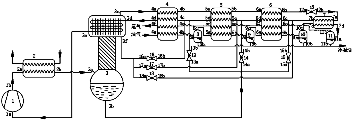
[0050] Such as figure 1 As shown, a rectification-type self-cascading low-temperature condensation oil-gas separation system includes a compressor 1, a condenser 2, a rectification device 3, a first heat exchanger 4, a second heat exchanger 5, and a third heat exchanger 6. Evaporator 7, first separator 8, second separator 9, third separator 10, fourth separator 11, first throttling element 12, second throttling element 13, third throttling element 14 , the fourth throttle element 15 , the fifth throttle element 16 , the sixth throttle element 17 and the seventh throttle element 18 .
[0051] The rectification device 3 includes a rectification column and a column top heat exchanger connected to the top of the rectification column, and a cooling pipeline is arranged in the column top heat exchanger. The first heat exchanger 4, the second heat exchanger 5, and the third heat exchanger 6 are all provided with a forward flow refrigerant pipeline, a return flow refrigerant pipeline...
Embodiment 2
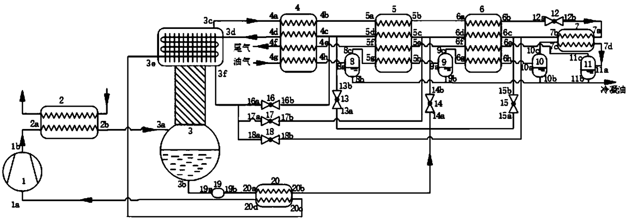
[0076] Such as figure 2 As shown, the connection mode and structure are the same as in Example 1, except that a dry filter 19 and a bottom heat exchanger 20 are provided at the liquid outlet at the bottom of the rectification device.
[0077] The bottom outlet of the rectifying device 3 is first connected with the drying filter 19 and the tank bottom heat exchanger 20 in sequence, and then connected with the three branches where the second throttling element 13, the third throttling element 14 and the fourth throttling element 15 are located. connected;
[0078] A high-pressure refrigerant pipeline and a low-pressure refrigerant pipeline are arranged in the tank bottom heat exchanger 19 . Specifically, the bottom liquid outlet 3b of the rectifying device 3 is connected with the inlet 19a of the drier filter 19, and the outlet 19b of the drier filter 19 is connected with the high-pressure refrigerant pipeline inlet 20a of the tank bottom heat exchanger 20; The high-pressure ...
Embodiment 3
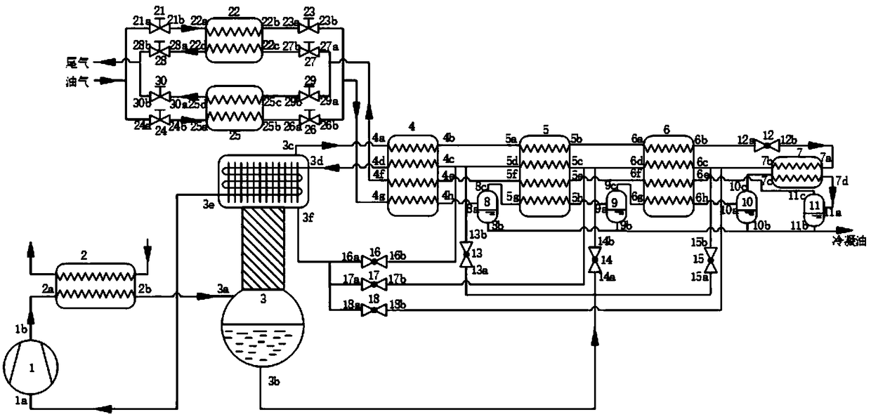
[0081] Such as image 3 As shown, the connection method and structure are the same as in Embodiment 1, except that a third heat exchanger unit is newly added.
[0082] The third heat exchanger unit includes a fourth heat exchanger 22, a fifth heat exchanger 25, a first shut-off valve 21, a second shut-off valve 23, a third shut-off valve 24, a fourth shut-off valve 26, and a fifth shut-off valve 27 , the sixth shut-off valve 28, the seventh shut-off valve 29 and the eighth shut-off valve 30, the fourth heat exchanger 22 and the fifth heat exchanger 25 are arranged in parallel, wherein the first shut-off valve 21 is linked with the second shut-off valve 23, the second shut-off valve The third stop valve 24 is linked with the fourth stop valve 26 , the fifth stop valve 27 is linked with the sixth stop valve 28 , and the seventh stop valve 29 is linked with the eighth stop valve 30 .
[0083]Specifically, oil and gas are first connected with the inlet 21a of the first cut-off va...
PUM
 Abstract
Description
Claims
Application Information
 - R&D Engineer
- R&D Manager
- IP Professional
- Industry Leading Data Capabilities
- Powerful AI technology
- Patent DNA Extraction
Browse by: Latest US Patents, China's latest patents, Technical Efficacy Thesaurus, Application Domain, Technology Topic, Popular Technical Reports.
© 2024 PatSnap. All rights reserved.Legal|Privacy policy|Modern Slavery Act Transparency Statement|Sitemap|About US| Contact US: help@patsnap.com