
A power-saving device for real-time improvement of power factor at the end of the power grid

A power-saving device and power factor technology, applied in circuit devices, emergency protection circuit devices for limiting overcurrent/overvoltage, emergency protection circuit devices, etc., can solve the problem of equipment output reduction, failure to achieve compensation, and increased power consumption Equipment and other problems to achieve the effect of improving load carrying capacity, avoiding inaccurate compensation, and reducing power loss

Active Publication Date: 2020-04-21
ZHEJIANG YONGYUAN XINNENG TECH CO LTD
View PDF4 Cites 0 Cited by
  • Summary
  • Abstract
  • Description
  • Claims
  • Application Information

AI Technical Summary

Problems solved by technology

However, at present, the capacitor cabinet can only be operated under the low voltage test of the transformer, and only the reactive power of the first stage is compensated, and the reactive power required at the end cannot be effectively compensated, and there is a hysteresis in the compensation, and the response time is too slow. The reactive power required at the end cannot be compensated in time. At the same time, the compensation of the capacitor cabinet has a stepwise nature. Since the compensation of the capacitor cabinet is in a stepped state, accurate compensation cannot be realized. It often happens that the power is over-compensated, and the power is not enough. Complementary phenomenon
Especially in the occasions where the harmonics are relatively serious, the use of capacitor cabinets for compensation will produce series or parallel resonance, amplify the harm of harmonics, and cause the capacitors in the capacitor cabinet to explode
Using capacitor cabinets for compensation, the head-end capacitor compensation has a certain hysteresis phenomenon, because the load of the terminal equipment is constantly changing, and the required reactive power is also different. Due to the hysteresis of the capacitor, the required reactive power cannot be accurately compensated. Therefore, the terminal power factor is low, which will increase the line loss in the line, reduce the output of the equipment, and increase the capacity of the electrical equipment; so a new type of power-saving device is needed in the market

Method used


Image

  • A power-saving device for real-time improvement of power factor at the end of the power grid
  • A power-saving device for real-time improvement of power factor at the end of the power grid
  • A power-saving device for real-time improvement of power factor at the end of the power grid

Examples


Embodiment 1

[0021] An energy-saving device for improving power factor at the end of a power grid in real time, comprising a chassis and an energy-saving device body disposed in the chassis, the power-saving device body comprising:

[0022] The integrated control unit automatically detects the current signal in the grid in real time through the acquisition unit, and then sends it to the control chip for precise calculation, so that the output compensation current changes with the change of the detected current;

[0023] Safety protection device, through the use of low-voltage control circuit to improve the safety of manual operation;

[0024] Bypass control unit, when the device is in the bypass state, it can automatically switch to the bypass state when it detects that the compensated reactive power meets the reactive power required by the end, so that the phenomenon of reactive power overcompensation will not occur. By controlling the contactor group When the power-saving device itself f...

Embodiment 2

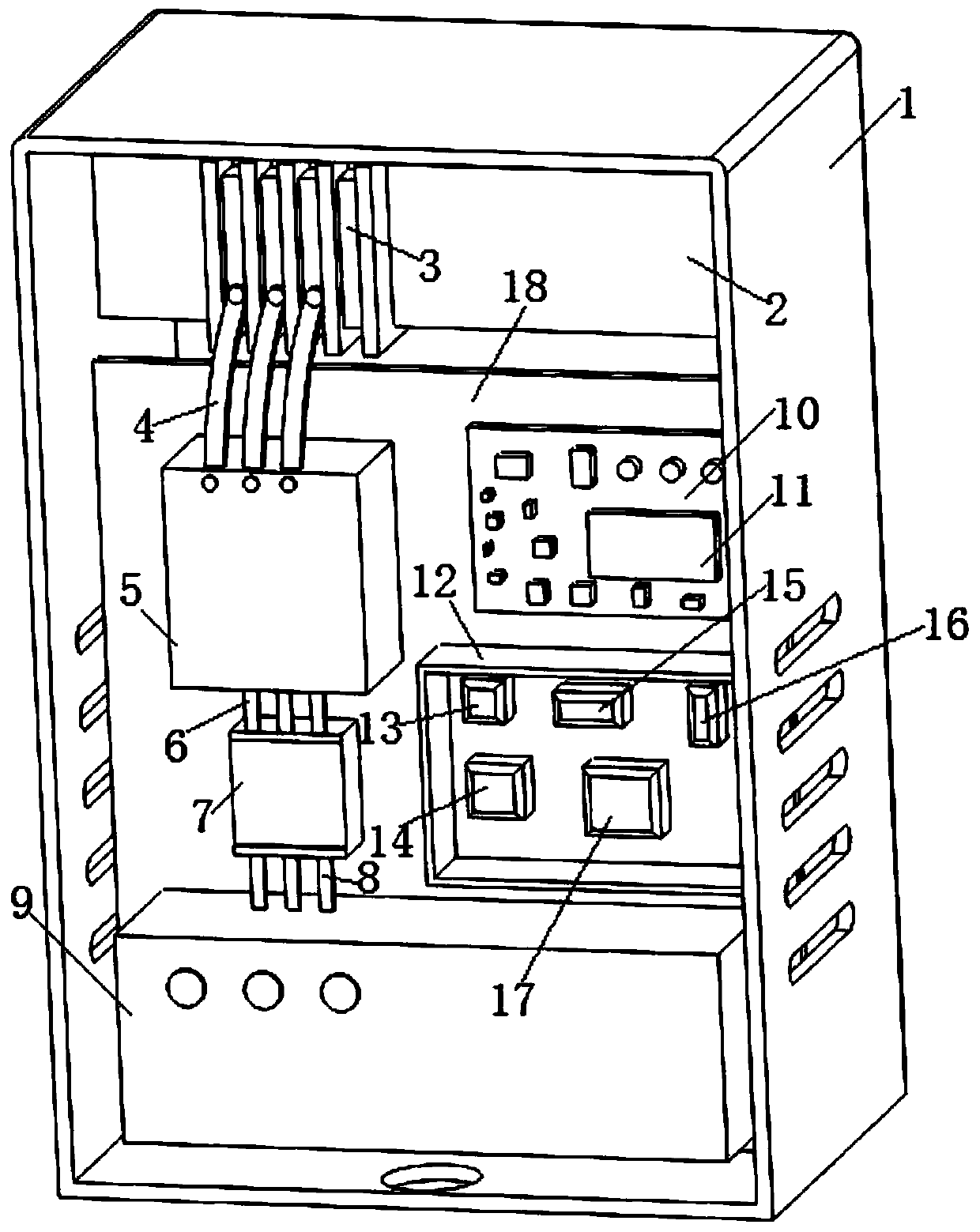
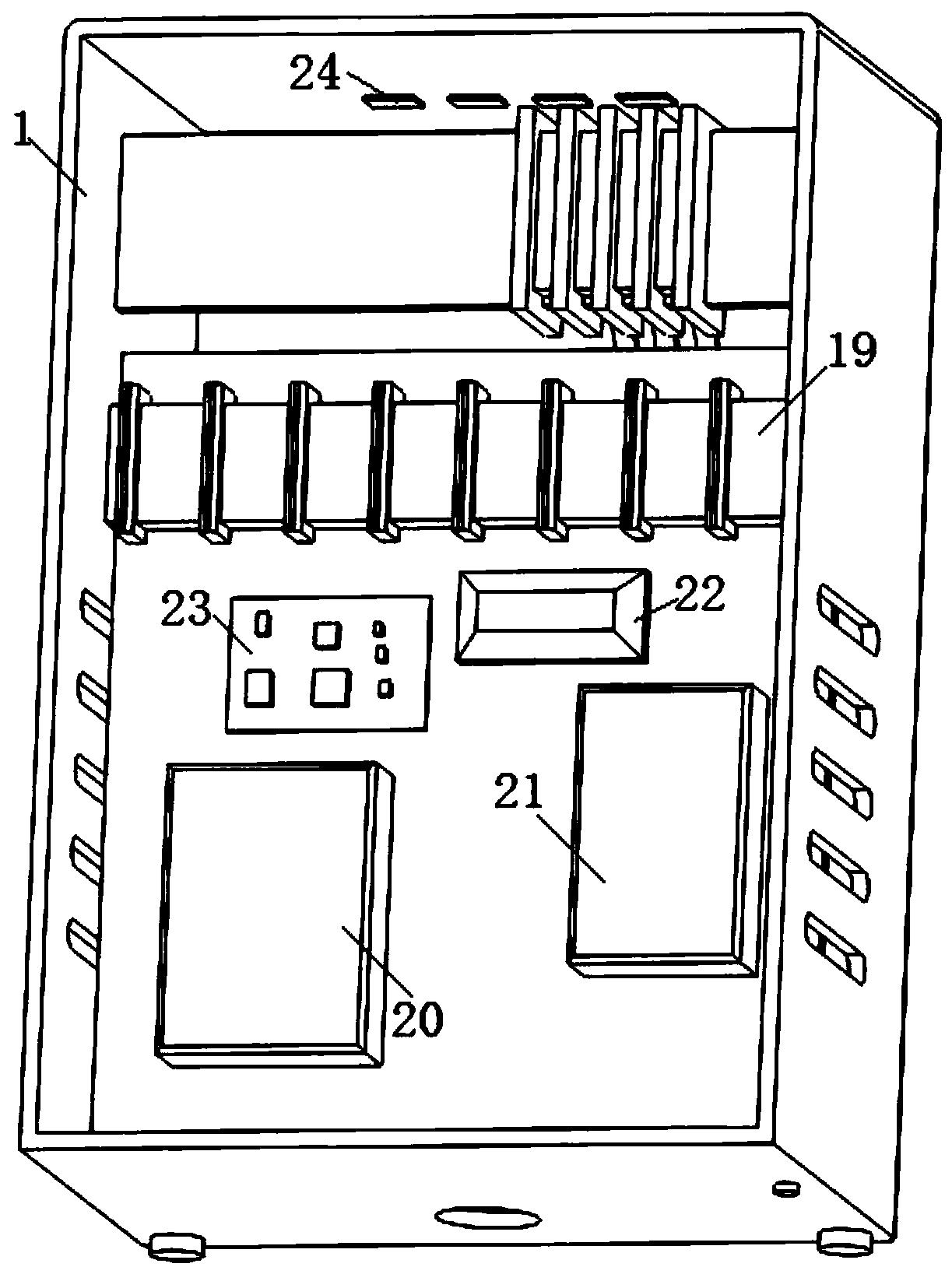
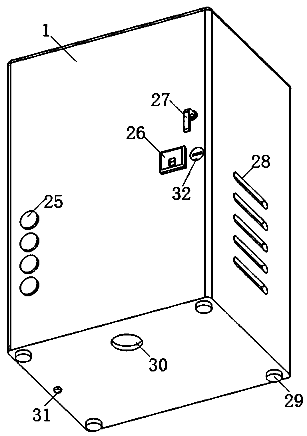
[0034] The device further includes a cabinet body 1; an installation partition 18 is installed in the middle of the interior of the cabinet body 1; a strut 2 is provided on the front side of the installation partition 18; A wiring device 3 is provided on the side; the terminal of the wiring device 3 is connected to a cable a4; the other end of the cable a4 is connected to a collection unit 5; the lower side of the collection unit 5 is provided with a bypass Control unit 7; a cable b6 is provided between the bypass control unit 7 and the acquisition unit 5; a cable c8 is connected to the lower part of the bypass control unit 7; the other end of the cable c8 is connected to There is a power-saving device body 9; one side of the acquisition unit 5 is provided with an integrated control unit 10; the integrated control unit 10 includes a control chip 11; the lower side of the integrated control unit 10 is equipped with a safety protection device 12. A surge control device 20 is ins...


PUM


Abstract

The invention discloses a power-saving device capable of improving a tail end power factor of a capacitance compensation cabinet. The power-saving device comprises a case and a power-saving device body, wherein the power-saving device body is arranged in the case and comprises an integrated control unit, a safety protection device, a bypass control unit, a sampling unit, a surge management device and a bypass switching control key, wherein the bypass switching control key is arranged outside the case and is used for manually switching a bypass / power-saving state. By the power-saving device, the reactive power required by a tail end of a power utilization device can be timely and accurately compensated, the response time is short, compensation can be provided according to demand on reactive power change required by the tail end, and an excessive compensation or under compensation phenomenon can be prevented.

Description

technical field [0001] The invention relates to the technical field of power-saving equipment, in particular to a power-saving device for improving the power factor at the end of a power grid in real time. Background technique [0002] At present, the capacitance compensation cabinet at this stage is usually installed in the voltage drop test operation of the transformer in the power distribution room, and generally it operates automatically under the control of power factor. The capacity of the capacitor and the number of capacitor banks are determined according to the different types of loads. However, at present, the capacitor cabinet can only be operated under the low voltage test of the transformer, and only the reactive power of the first stage is compensated, and the reactive power required at the end cannot be effectively compensated, and there is a hysteresis in the compensation, and the response time is too slow. The reactive power required at the end cannot be co...

Claims


Application Information

Patent Timeline
Patent Type & Authority Patents(China)
IPC IPC(8): H02J3/18H02J3/01H02J3/12H02H9/02H02H9/04
CPCH02H9/005H02H9/02H02H9/04H02J3/01H02J3/12H02J3/18Y02E40/30Y02E40/40
Inventor 陈勇华金科冉赵洋
Owner ZHEJIANG YONGYUAN XINNENG TECH CO LTD
Learn More