
Constant power ballasting component

A constant power and ballast technology, applied in the direction of electrical components, electrical component structure associations, transformer/inductor parts, etc., can solve the problems of large power consumption, large volume, high manufacturing cost, etc., and achieve the effect of saving manufacturing costs

Inactive Publication Date: 2017-06-09
NINGBO AUPUL TELECOMM EQUIP +1
View PDF5 Cites 1 Cited by
  • Summary
  • Abstract
  • Description
  • Claims
  • Application Information

AI Technical Summary

Problems solved by technology

[0003] However, the CWA or CWI flux leakage ballasts in the prior art have the disadvantages of high manufacturing cost, low efficiency, large power consumption, and large volume

Method used


Image

  • Constant power ballasting component
  • Constant power ballasting component
  • Constant power ballasting component

Examples


Embodiment Construction

[0025] Embodiments of the present invention will now be described in detail with reference to the accompanying drawings. Reference will now be made in detail to the preferred embodiments of the invention, examples of which are illustrated in the accompanying drawings. Wherever possible, the same numbers will be used throughout the drawings to refer to the same or like parts. In addition, although the terms used in the present invention are selected from well-known and commonly used terms, some terms mentioned in the description of the present invention may be selected by the applicant according to his or her judgment, and the detailed meanings thereof are set forth herein described in the relevant section of the description. Furthermore, it is required that the present invention be understood not only by the actual terms used, but also by the meaning implied by each term.

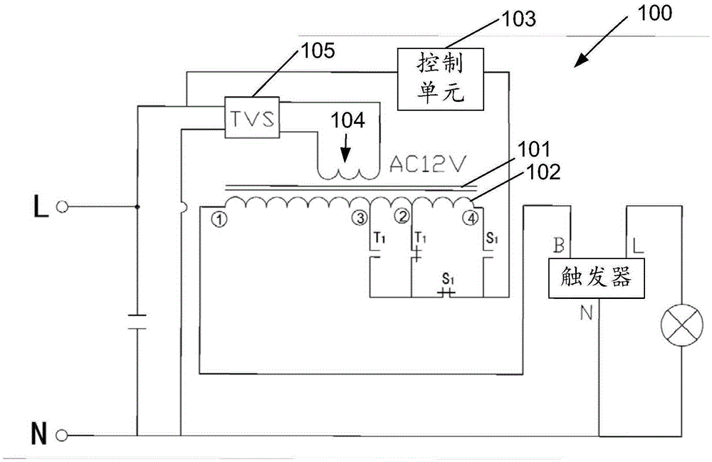
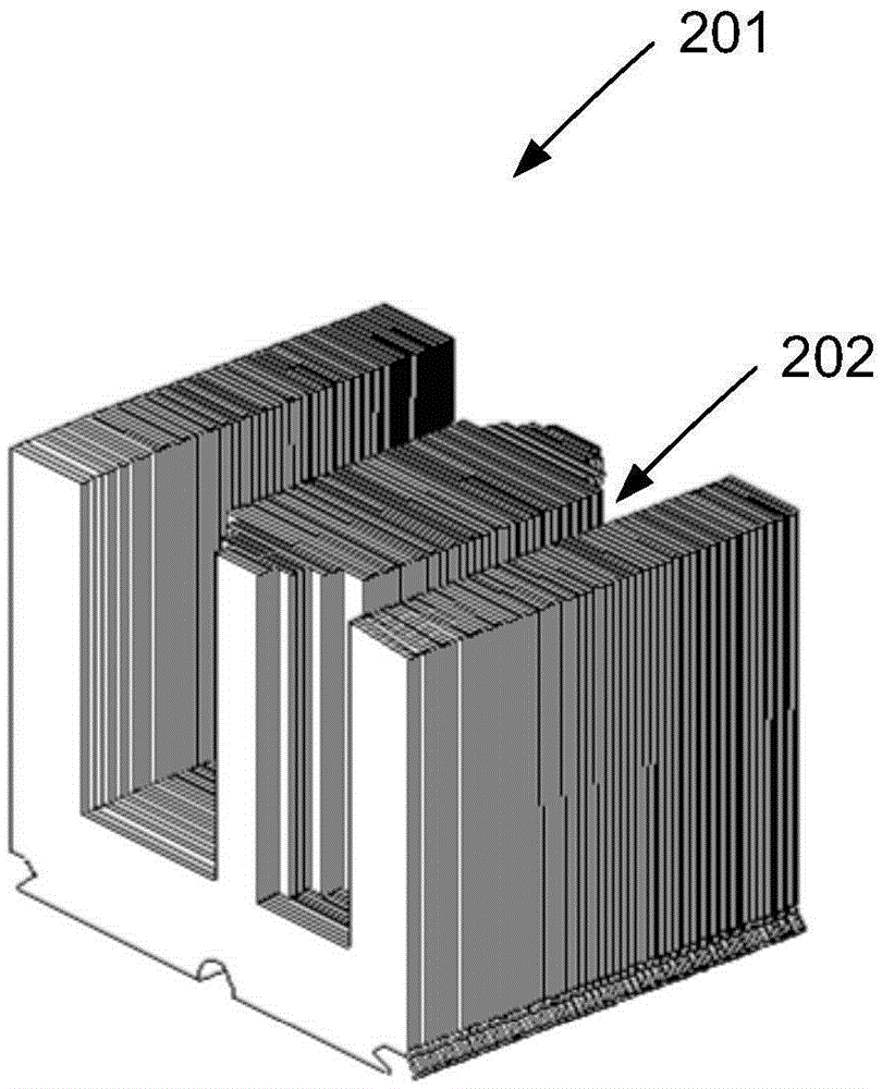
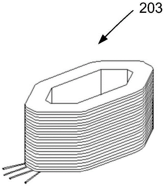
[0026] first reference figure 1 , which shows the basic principle of the constant power ballast assem...


PUM


Abstract

The invention provides a constant power ballasting component, comprising: a magnetic core; a main coil arranged in the magnetic core, wherein the main coil at least includes a first tap, a second tap, a third tap and a fourth tap, wherein a coil of first number of turns is arranged between the first tap and the third tap, a coil of second number of turns is arranged between the first tap and the second tap, and a coil of third number of turns is arranged between the first tap and the fourth tap; a control unit that detects an input voltage and switches on one of the second, third and fourth taps and the first tap selectively according to the input voltage. The constant power ballasting component allows the corresponding number of turns to be adjusted and the tapping to be performed during winding of a choke coil according to voltage fluctuation, so that a lamp is kept operating substantially under the rated power to save energy.

Description

technical field [0001] The invention relates to a ballast assembly, in particular to a constant power ballast assembly suitable for high-intensity gas discharge lamps. Background technique [0002] At present, in areas with large voltage fluctuations, CWA or CWI flux leakage constant power inductive ballasts with magnetic shunts are generally used in the market to maintain the rated power of the lamp to ensure the lighting quality and prolong the life of lighting appliances. [0003] However, the CWA or CWI flux leakage ballast in the prior art has the disadvantages of high manufacturing cost, low efficiency, large power consumption, and large volume. Contents of the invention [0004] Aiming at the actual application needs in the industry, the present invention proposes a brand new constant power ballast assembly. [0005] Specifically, the present invention proposes a constant power ballast assembly, including: [0006] magnetic core; [0007] The main coil is arrange...

Claims


Application Information

Patent Timeline
Patent Type & Authority Applications(China)
IPC IPC(8): H01F38/10H01F27/28H01F29/02H01F27/40H01F27/245
Inventor 周尧达张乃铫
Owner NINGBO AUPUL TELECOMM EQUIP
Learn More