
Injected electron collector

An electron collector and electron collection technology, applied in nuclear power generation, greenhouse gas reduction, nuclear reactors, etc., to achieve the effects of quasi-injected electron density adjustment and angle adjustment, simple mechanical structure, and high precision

Active Publication Date: 2017-06-09
HUAZHONG UNIV OF SCI & TECH
View PDF5 Cites 2 Cited by
  • Summary
  • Abstract
  • Description
  • Claims
  • Application Information

AI Technical Summary

Problems solved by technology

Therefore, it is the key to realize electron drift injection to reduce ring voltage start-up by improving and obtaining accurate electron injection rate, as well as the optimal electron density of electron injection source and the optimal injection angle of electron drift injector at this electron injection rate. The injected electrons in the tokamak during electron drift injection must be collected; however, there is currently no device for collecting the drift injected electrons

Method used


Image

  • Injected electron collector
  • Injected electron collector
  • Injected electron collector

Examples


Embodiment Construction

[0025] In order to make the objectives, technical solutions and advantages of the present invention clearer, the following further describes the present invention in detail with reference to the accompanying drawings and embodiments. It should be understood that the specific embodiments described herein are only used to explain the present invention, but not to limit the present invention. In addition, the technical features involved in the various embodiments of the present invention described below can be combined with each other as long as they do not conflict with each other.

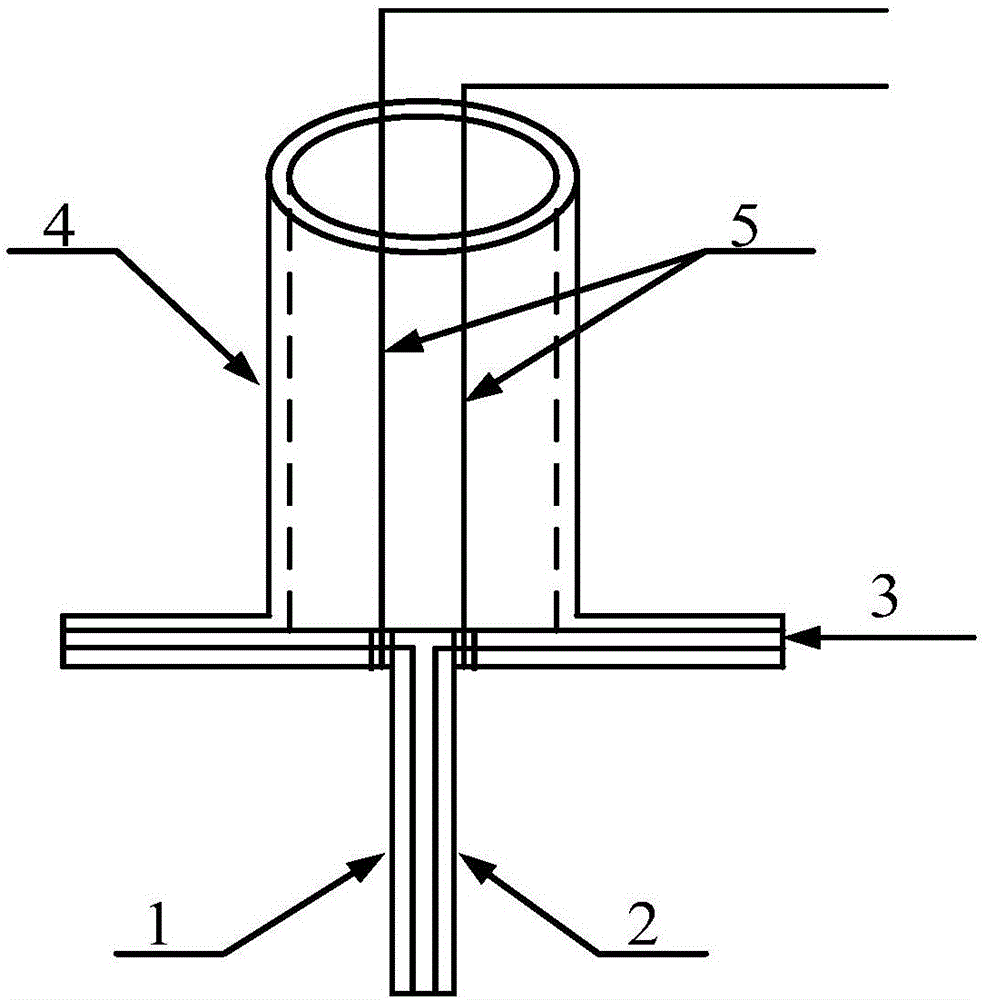
[0026] The function and principle of the injected electron collector provided by the embodiment are as follows figure 1 Shown; including sequentially connected injected electron collection unit, bias power supply unit, data acquisition and processing unit and adjustment unit;

[0027] The injected electron collection unit collects the injected electrons in the tokamak device under the action of the bias ...


PUM

PropertyMeasurementUnit
Thicknessaaaaaaaaaa

Abstract

The invention discloses an injected electron collector. The injected electron collector comprises an injected electron collection unit, a bias power supply unit, a data acquisition processing unit, and an adjusting unit. The injected electron collection unit is inserted in a device by a window of a tokamak device, and is capable of moving upwards and downwards in the device, and is used to collect injected electrons. The bias power supply unit is used to provide bias for the injected electrons, and is used to convey the injected electrons to the data acquisition processing unit. The data acquisition processing unit is used to acquire injected electron current, and is used to determine the number of the collected injected electrons according to the injected electron current. An electron injection source and an injector angle adjusting unit are used to adjust the electron density of the electron injection source and the injection angle of the electron drift injector in a self-adaptive manner according to the difference between the injected electron numbers in a fixed interval, and when the tokamak device has a maximum injection electron rate, the electron injection source has the optimal electron density and the electron drift injector has the optimal injection angle correspondingly.

Description

Technical field [0001] The invention belongs to the technical field of collecting electrons injected by a tokamak device, and more specifically, relates to an injected electron collector used for an electron drift injection experiment of a tokamak device. Background technique [0002] In the research process of controllable nuclear fusion, it is of great significance to realize the low-loop voltage start of the Tokamak device. It can save the number of volt-seconds of the heating field consumed in the discharge start stage, thereby creating conditions for extending the duration of plasma discharge , It can reduce the requirements for the power supply of the heating field and save a lot of money. Especially for large-scale superconducting tokamak devices of the current and next generations, due to the requirements for the safe operation of superconducting poloidal field coils and to prevent the frequent occurrence of superconducting coil quenches, the effect of electron drift inje...

Claims


Application Information

Patent Timeline
IPC IPC(8): G21B1/25
CPCG21B1/25Y02E30/10
Inventor 杨州军孙宗昌蔡豪谢先立阮博文
Owner HUAZHONG UNIV OF SCI & TECH
Learn More