
TOF camera calibration and correction system and device and method thereof

A technology of TOF camera and calibration method, applied in the field of TOF, can solve the problems of complicated calibration of TOF camera, defects of calibration and correction methods, measurement standard deviation, etc.

Active Publication Date: 2017-06-09
NINGBO SUNNY OPOTECH CO LTD
View PDF2 Cites 23 Cited by
  • Summary
  • Abstract
  • Description
  • Claims
  • Application Information

AI Technical Summary

Problems solved by technology

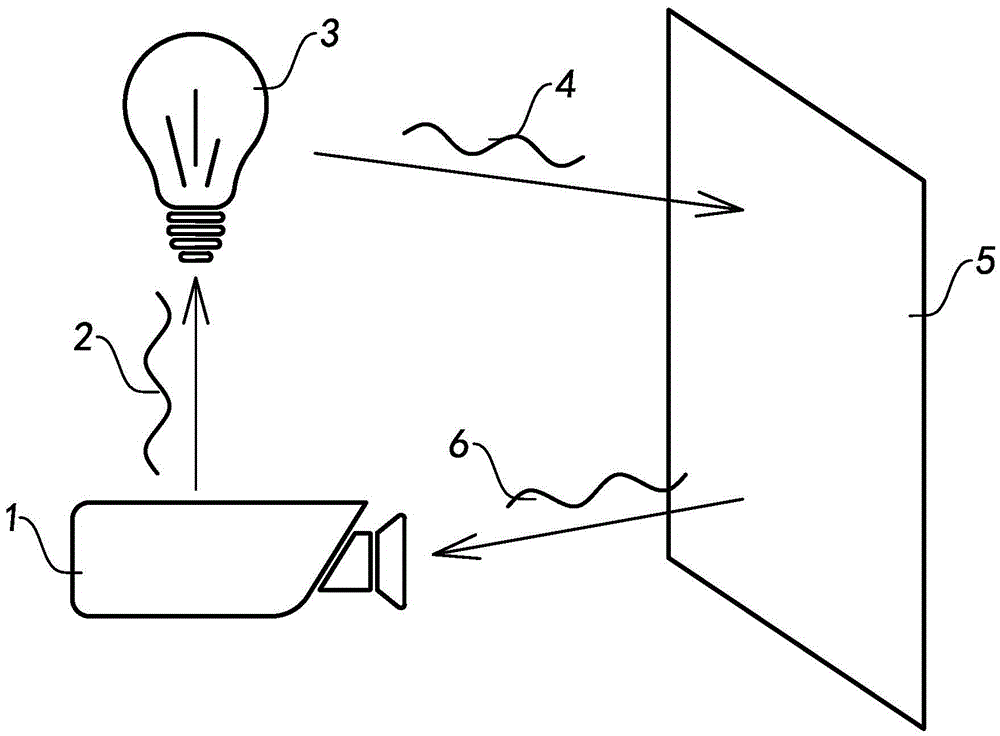
The light wave emitted by the active light source reaches the target object, is reflected back by the target object, and is received by the TOF camera. Since the waveform of the reference signal and the received signal are assumed to be standard waveforms when calculating the distance and amplitude, the actual reference signal and received signal The signal is not a complete standard waveform, and there are DC components, high-order harmonics and non-harmonic signals, etc. The existence of these factors will inevitably interfere with the distance measurement results
[0006] 2. Errors caused by changes in incident light intensity
[0007] 3. Errors caused by different integration times
A large number of existing research results show that the error caused by different integration times is different, and when the integration time is too long or too short, it will have a great impact on the measurement standard deviation
[0008] In addition, there are many factors that affect the TOF camera. For example, due to the limitation of the manufacturing process, each pixel cannot be exactly the same, so the offset of each pixel will also bring errors
[0009] Since there are many factors affecting the error of the TOF camera, and the influencing factors are not completely independent, the calibration of the TOF camera is extremely cumbersome, and there are many defects in the existing calibration and correction methods
For example, using the univariate calibration method, it is difficult to quickly and accurately obtain the calibration parameters by correcting different influencing factors.

Method used


Image

  • TOF camera calibration and correction system and device and method thereof
  • TOF camera calibration and correction system and device and method thereof
  • TOF camera calibration and correction system and device and method thereof

Examples


Embodiment Construction

[0057] The following description serves to disclose the present invention to enable those skilled in the art to carry out the present invention. The preferred embodiments described below are only examples, and those skilled in the art can devise other obvious variations. The basic principles of the present invention defined in the following description can be applied to other embodiments, variations, improvements, equivalents and other technical solutions without departing from the spirit and scope of the present invention.

[0058] The TOF camera is a 3D camera based on the photon time-of-flight ranging principle, and is composed of an illumination source, a lens, and a photosensitive element. There are two types of signal modulation: pulse light modulation and continuous wave modulation. Among them, the pulsed light modulation method obtains distance information by directly measuring the time-of-flight of light. The continuous wave modulation method takes the incident ligh...


PUM


Abstract

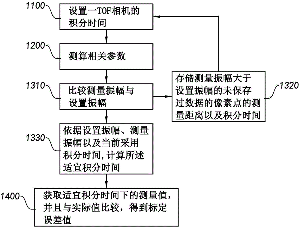
The invention discloses a TOF camera calibration and correction system and a device and method thereof, wherein the TOF calibration method comprises the steps: (A), setting the integration time of a TOF camera; (B), measuring the related parameters; (C), obtaining the proper integration time according to the related parameters; (D), obtaining a measurement value in the proper integration time, comparing the measurement value with an actual value, and obtaining a calibration error value. The TOF camera correction system comprises a calibration unit and a correction unit. The calibration unit obtains the proper integration time of the TOF camera, so as to obtain the stable calibration error. The correction unit corrects the calibration error of the calibration unit.

Description

technical field [0001] The present invention relates to the technical field of TOF, and further relates to a TOF camera calibration and correction system and its equipment and method. Background technique [0002] The 3D camera based on the TOF (Time-Of-Flight) theory is one of the research hotspots in today's technology. The TOF 3D camera can acquire grayscale images and distance images at the same time, and has gradually appeared in gesture control, 3D modeling, and automobiles. In the field of systems such as radar and robot vision. [0003] TOF camera technology is one of the most prominent optical three-dimensional measurement technologies. Its basic principle is: the light emitted by the active light source is reflected by the object and captured by the TOF camera. The phase difference is used to calculate the distance between the subject and the TOF camera, and while obtaining the depth information of the subject, the TOF camera also captures grayscale information. ...

Claims


Application Information

Patent Timeline
Patent Type & Authority Applications(China)
IPC IPC(8): G06T7/80
Inventor 王城特王宗泽赵俊能
Owner NINGBO SUNNY OPOTECH CO LTD
Learn More