
Bent head structure used on pipe bending machine

A pipe bender and bending technology, which is applied in the field of bending head structure, can solve the problems of heavy overall weight, difficult wiring, slow speed, etc., and achieve the effects of improving the processing yield, simple structure, and convenient installation and use

Inactive Publication Date: 2017-06-09
武汉思瑞法机器人制造有限公司
View PDF6 Cites 0 Cited by
  • Summary
  • Abstract
  • Description
  • Claims
  • Application Information

AI Technical Summary

Problems solved by technology

[0003] The movement of the bending die in the prior art is generally directly driven by the bending die motor with the lead screw mechanism, and the general bending die motor is directly installed on the left or right side of the die base of the bending die. The disadvantage of this technical solution is Difficult to route, always exposed outside, and the overall weight is large, slow start, slow stop, slow speed

Method used

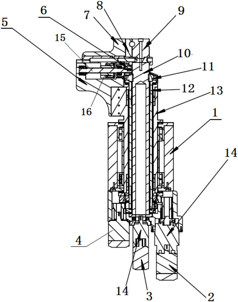
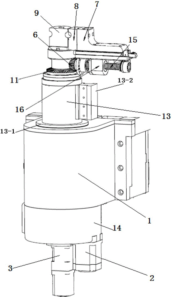

Image

  • Bent head structure used on pipe bending machine
  • Bent head structure used on pipe bending machine
  • Bent head structure used on pipe bending machine

Examples


Embodiment Construction

[0021] In order to make the object, technical solution and advantages of the present invention clearer, the present invention will be further described in detail below in conjunction with the accompanying drawings and embodiments. It should be understood that the specific embodiments described here are only used to explain the invention, not to limit the invention.

[0022] Such as figure 1 and figure 2 A kind of bending head structure that is used on the pipe bending machine shown is known, and the present invention comprises bending die, and bending die comprises bending die base 1, the center column 10 that is connected with bending die head 9, is used to drive the bending of center column 10 revolutions. Die motor 3, the three are coaxially arranged; the central column 10 is coaxially arranged inside the bending die base 1 and its end is located outside the bending die base 1 to realize pipe bending; the fixed end of the bending die motor 3 is affixed to the bending die ...

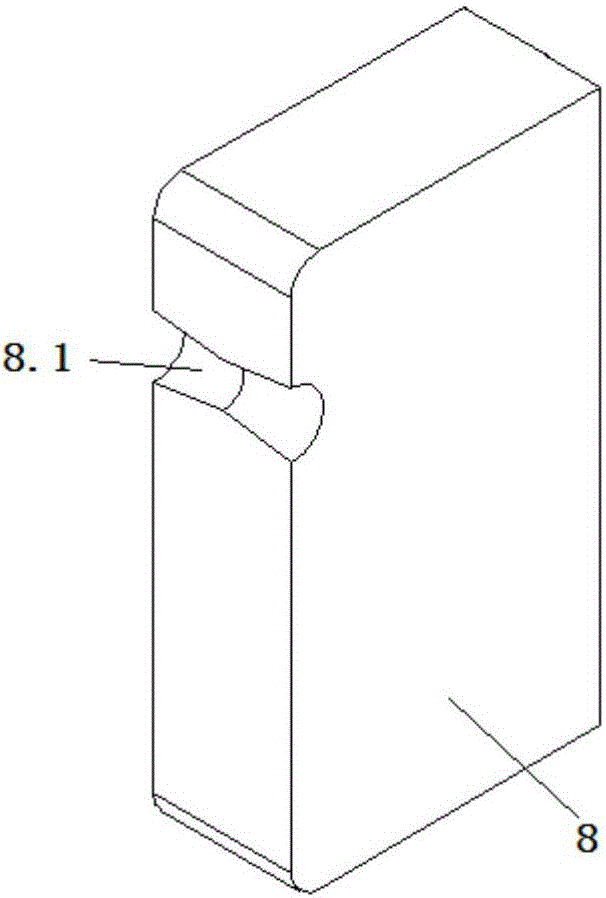

PUM


Abstract

The invention discloses a bending head structure used on a pipe bending machine, comprising a bending die, the bending die includes a bending die base and a central column connected with a bending die head; the central column and the bending die base are coaxially arranged; the features are: The center column is coaxially fitted with the hollow shaft of the pressure tube and the outer ring of the elbow along its radial direction from the inside to the outside; the outer ring of the elbow is connected with a bending mechanism; The seat and the bending rod that can cooperate with the bending die to realize the bending of the pipe material; the bending rod is slidably connected to the base of the bend; the base of the bend is provided with a screw mechanism for driving the movement of the bend rod; the screw mechanism passes through A set of bevel gear mechanism is connected with the pressure tube hollow shaft. The invention is simple in structure and easy to install and use. While effectively realizing the functions of rolling, pressing and winding bending of the pipe material, it ensures the interference of the parts of the bending die on the pipe material, making the structure of the pipe bending machine more stable. compact.

Description

technical field [0001] The invention relates to a bending head structure, which belongs to the technical field of auxiliary parts of pipe bending machines, and in particular to a bending head structure used in pipe bending machines. Background technique [0002] A pipe bender is a device used to bend a slender straight pipe into a three-dimensional curved pipe. The pipe bender is widely used in automobile, refrigeration and other fields, and is used to manufacture three-dimensional bent pipes. The core part of the pipe bending machine is the bending die and the bending die. [0003] The movement of the bending die in the prior art is generally directly driven by the bending die motor with the lead screw mechanism, and the general bending die motor is directly installed on the left or right side of the die base of the bending die. The disadvantage of this technical solution is It is not easy to route the wires, it is always exposed outside, and the overall weight is heavy, ...

Claims


Application Information

Patent Timeline
Patent Type & Authority Applications(China)
IPC IPC(8): B21D7/024B21D37/10
CPCB21D7/024B21D37/10
Inventor 熊震左江桥郑红讯李威杜晓峰杨韦闻华浩
Owner 武汉思瑞法机器人制造有限公司
Learn More