self-propelled vacuum cleaner
A vacuum cleaner and self-propelled technology, which is applied to the installation of vacuum cleaners, household appliances, and electrical equipment. It can solve the problems that the side brush cannot be used to sweep out and remove dust, and the side brush cannot reach it, so that the structure will not be complicated. The effect that the number of parts does not increase
- Summary
- Abstract
- Description
- Claims
- Application Information
AI Technical Summary
Problems solved by technology
Method used
Image
Examples
Embodiment approach 1
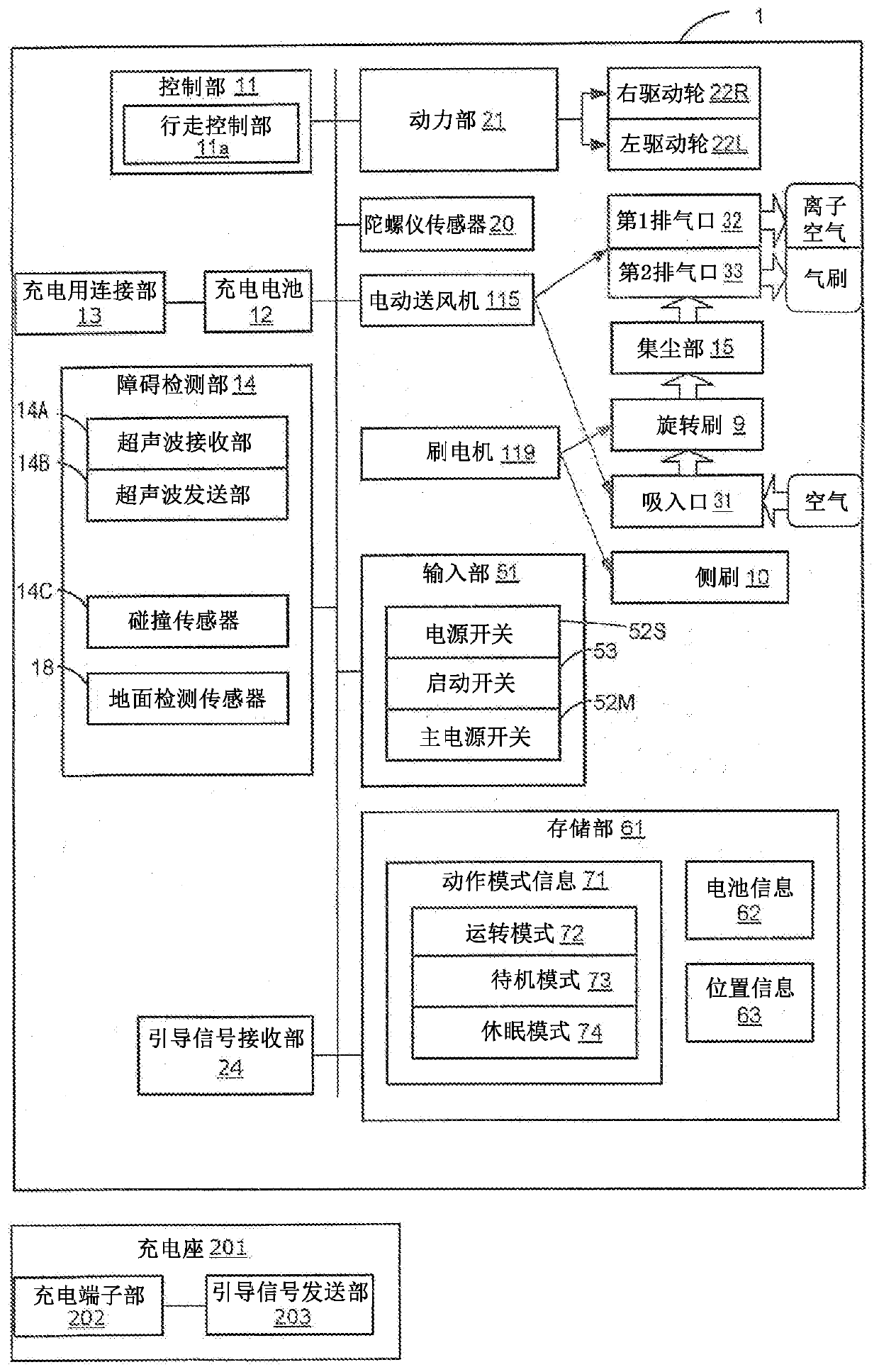
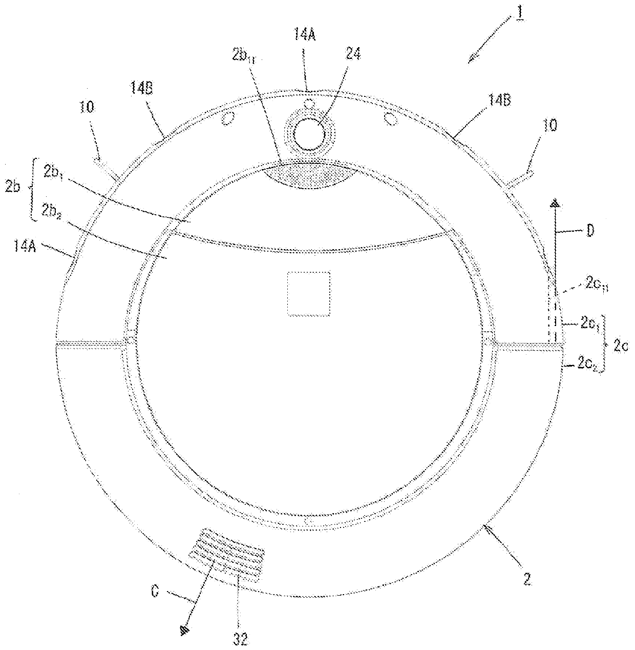
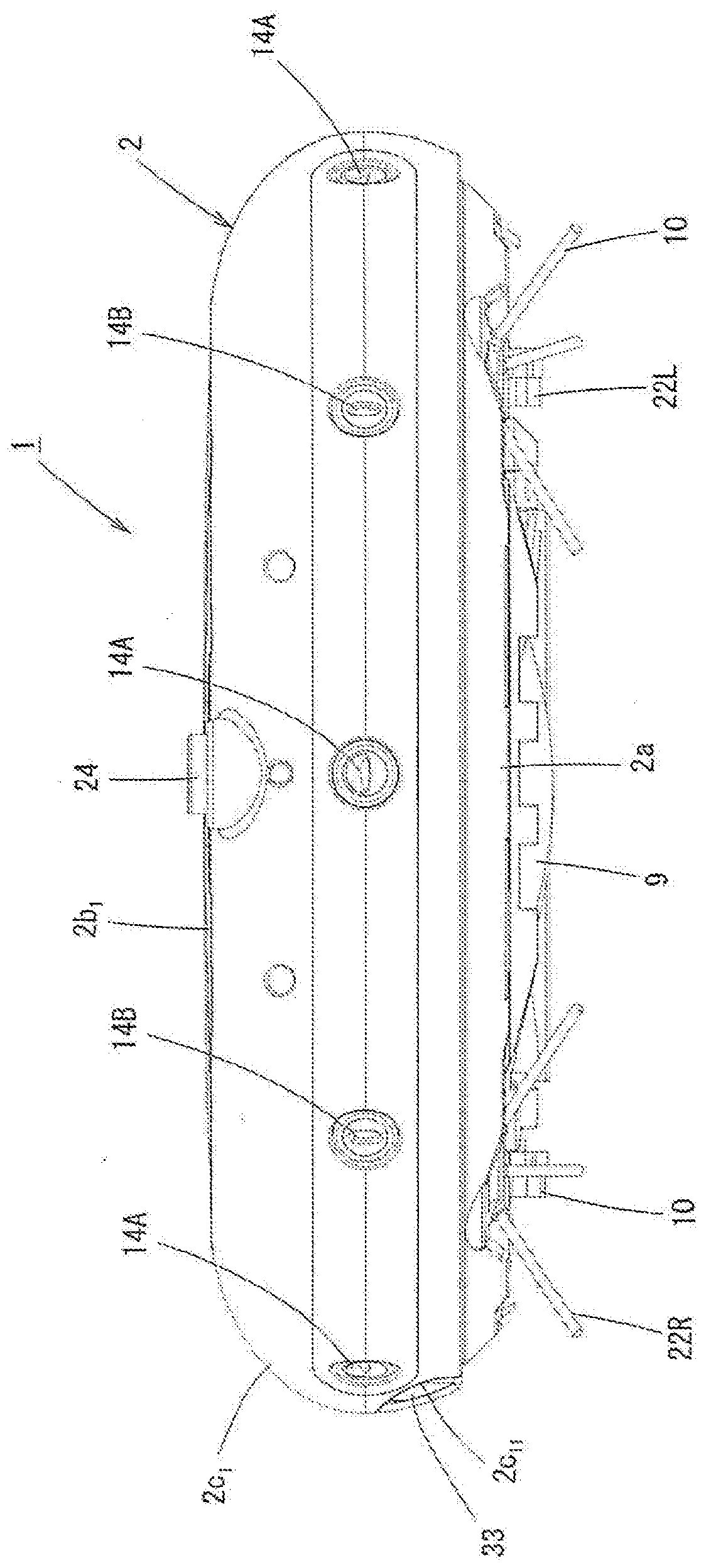
[0035] figure 1 It is a block diagram showing the electrical configuration of the self-propelled (vacuum) cleaner according to Embodiment 1 of the present invention. in addition, figure 2 It is a top view of the self-propelled vacuum cleaner according to Embodiment 1 of the present invention, and FIG. 3 is figure 1 The front view of the self-propelled vacuum cleaner shown, Figure 4 yes figure 1 A side view of the self-propelled vacuum cleaner shown, Figure 5 yes figure 1 The rear view of the self-propelled vacuum cleaner shown, Figure 6 yes figure 1 Bottom view of the self-propelled vacuum cleaner shown. in addition, Figure 7 yes figure 1 A top sectional view of the self-propelled vacuum cleaner shown, Figure 8 yes figure 1 Another top sectional view of the self-propelled vacuum cleaner shown. in addition, Figure 9 yes figure 1 A side sectional view of the self-propelled vacuum cleaner shown, Figure 10 It is a side sectional view of the self-pro...
Embodiment approach 2
[0097] In Embodiment 1, the rear half 2c of the side plate 2c of the box 2 is illustrated as an example. 2 and the ribs 2d provided on the inner structural wall 2d 1 、2d 2 In the case of forming the second exhaust air passage 35, it is also possible to install various components on the internal structure wall 2d and the rear half 2c of the side plate 2c. 2 A gap is formed between them to form a second exhaust air path.
Embodiment approach 3
[0099] In the case of Embodiment 1, since the output of the electric blower 115 is constant, the airflow F from the second exhaust port 33 1 The air volume is also fixed.
[0100] Therefore, in Embodiment 3, it may be that when Figure 11 (A) and Figure 11 As shown in (B), in the self-propelled vacuum cleaner 1, when the front ultrasonic receiving unit 14A detects the front wall W2, the output of the electric blower 115 is increased (for example, 1.3 to 1.5 times) than the normal level, and accordingly , so that the air flow F blown out from the second exhaust port 33 2 The air volume increases. Thereby, the cleaning force with respect to the corner part K where the dust Q tends to accumulate can be improved. Moreover, when the front ultrasonic wave receiving part 14A no longer detects a wall surface, the output of the electric blower 115 will return to a normal level.
PUM
 Abstract
Description
Claims
Application Information
 - R&D
- Intellectual Property
- Life Sciences
- Materials
- Tech Scout
- Unparalleled Data Quality
- Higher Quality Content
- 60% Fewer Hallucinations
Browse by: Latest US Patents, China's latest patents, Technical Efficacy Thesaurus, Application Domain, Technology Topic, Popular Technical Reports.
© 2025 PatSnap. All rights reserved.Legal|Privacy policy|Modern Slavery Act Transparency Statement|Sitemap|About US| Contact US: help@patsnap.com


