Circuit board mounting and fastening method

A circuit board and fastening technology, applied in the field of circuit board installation and fastening, can solve the problems of low installation efficiency, inconvenient operation, and a large number of connecting screws, and achieve high installation reliability, reduce installation costs, and improve installation efficiency. Effect

Active Publication Date: 2017-05-31
JIANGXI HONGDU AVIATION IND GRP
View PDF5 Cites 2 Cited by
  • Summary
  • Abstract
  • Description
  • Claims
  • Application Information

AI Technical Summary

Problems solved by technology

[0004] The purpose of the present invention is to provide a circuit board installation and fastening method to solve the problems of the existing installation method, such as the large number of connecting screws, low installation efficiency and inconvenient operation, to realize the installation and disassembly of the circuit board in a narrow space, and the connection strength meets the impact vibration environmental requirements with high reliability

Method used


Image

  • Circuit board mounting and fastening method
  • Circuit board mounting and fastening method
  • Circuit board mounting and fastening method

Examples


Embodiment 1

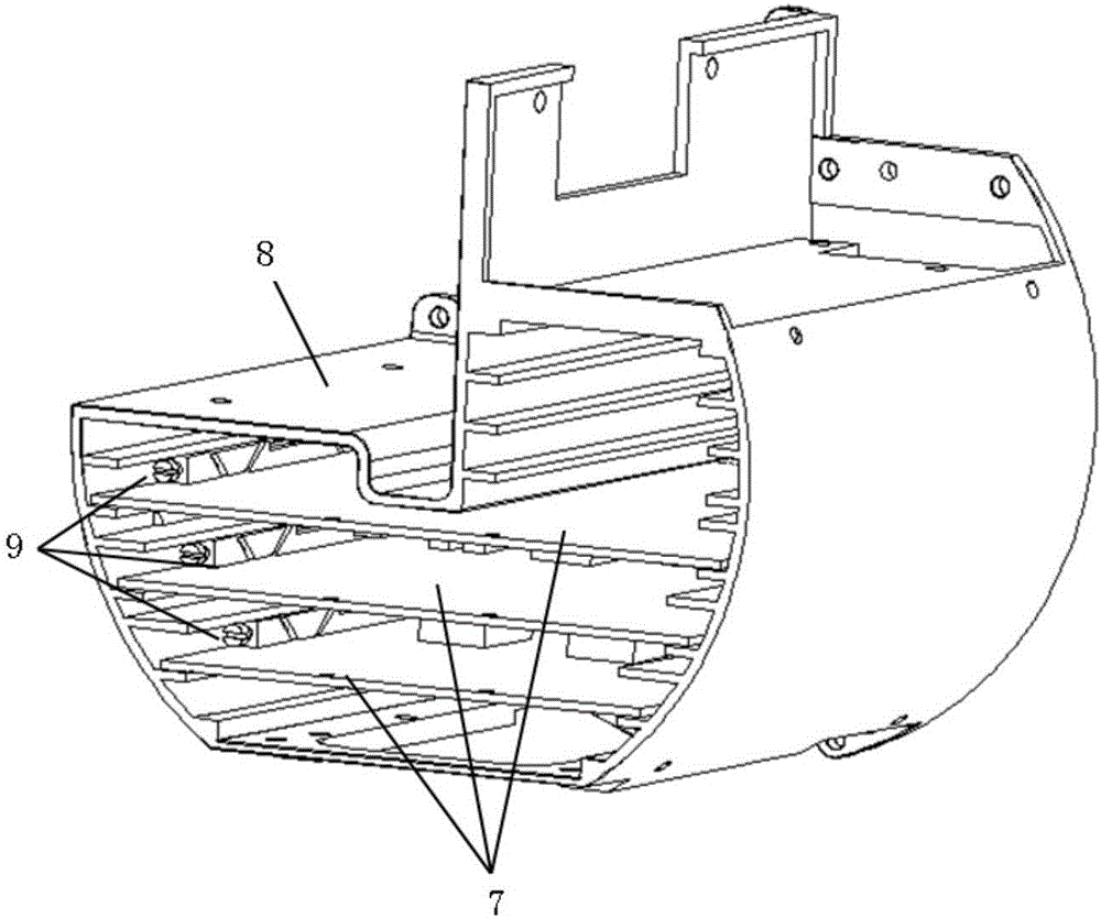
[0044] 1. Design and make locking strip 9

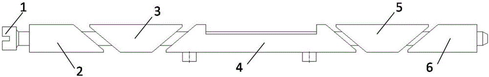
[0045] The locking bar includes screw 1, fixed block 1, movable block 1, fixed mounting block 4, movable block 5, fixed block 2, 6. Screw 1 is a long threaded rod with external threads.

[0046] The fixed block one 2 is a wedge-shaped structure with a right-angled trapezoid in cross section. The wedge angle of the inclined surface is 30°, and a circular through hole is provided on the rectangular side

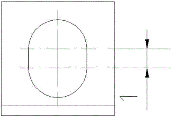
[0047] The movable block 3 is a wedge-shaped structure with an inverted trapezoid in section. The wedge angle of the inclined surface is 30°, which is consistent with the inclined wedge angle of the fixed block 2. The inclined surfaces of the movable block 3 and the fixed block 2 are parallel to each other. 3 center set up The waist-shaped hole, the center distance is 1mm, such as image 3 Shown

[0048] The movable block two 5 and the movable block one 3 belong to the same parts and have the same structural characteristics;

[0049] The fi...

Embodiment 2

[0057] 1 Design and make the locking strip 9

[0058] The locking bar includes screw 1, fixed block 1, movable block 1, fixed mounting block 4, movable block 5, fixed block 2, 6. Screw 1 is a long threaded rod with external threads.

[0059] The fixed block one 2 is a wedge-shaped structure with a right-angled trapezoid in cross section. The wedge angle of the inclined surface is 20°, and a circular through hole is provided on the side of the rectangle.

[0060] The movable block 3 is a wedge-shaped structure with an inverted trapezoid in cross section. The wedge angle of the inclined surface is 20°, which is consistent with the inclined wedge angle of the fixed block 2. The inclined surfaces of the movable block 3 and the fixed block 2 are parallel to each other. 3 center set up The waist-shaped hole, the center distance is 1mm, such as image 3 Shown

[0061] The movable block two 5 and the movable block one 3 belong to the same parts and have the same structural characteristics;...


PUM


Abstract

The invention discloses a circuit board mounting and fastening method, and relates to the technical field of integrated mounting and fastening of missile-borne electronic equipment of an air vehicle. The missile-borne electronic equipment is a constituent part of a missile weapon system, and a missile is compact in space, so that the mounting of the electronic equipment on the missile encounters a problem of space limitation; and meanwhile, for realizing convenience in dismounting, the missile-borne electronic equipment is integrated, and after integration, the space for mounting the electronic equipment is narrower and smaller, so that higher demand on the mounting way of the electronic equipment is required. The existing mounting way, due to a relatively large number of connecting screws, is relatively low in mounting efficiency and inconvenient to operate, and the same problems exist in disassembling. By adoption of the mounting and fastening method disclosed by the invention, a circuit board can be mounted in a cabin in a relatively convenient and rapid manner; the mounting and disassembling of the circuit board can be realized just by screwing a threaded rod in one direction; and in addition, the mounting reliability is high, impact vibration in a complex working condition can be satisfied, the mounting efficiency is greatly improved, and the mounting cost is lowered.

Description

Technical field [0001] The invention relates to a circuit board installation and fastening method, which relates to the technical field of integrated installation and fastening of electronic equipment on board missiles of aircraft. Background technique [0002] Missile-borne electronic equipment is an indispensable part of the missile weapon system, and the installation space on the missile is compact, causing the installation of these equipment on the missile to face the problem of limited space. In order to make the size of the missile as small as possible, the structure is simpler, and for the convenience of disassembly and assembly, the missile-borne electronic equipment is integrated. After the integration, the space left for the installation of electronic equipment will inevitably be narrower, which places higher requirements on the installation form of electronic equipment. [0003] The existing installation method has low installation efficiency and inconvenient operation ...

Claims


Application Information

Patent Timeline
Patent Type & Authority Applications(China)
IPC IPC(8): H05K7/14
CPCH05K7/1402
Inventor 马俊飞张效义康龙辉李建华周盛蒋若冰闫卫涛谢锦涛瞿绍奇周平平
Owner JIANGXI HONGDU AVIATION IND GRP
Why Eureka
Try Eureka