
Flexible electronic equipment

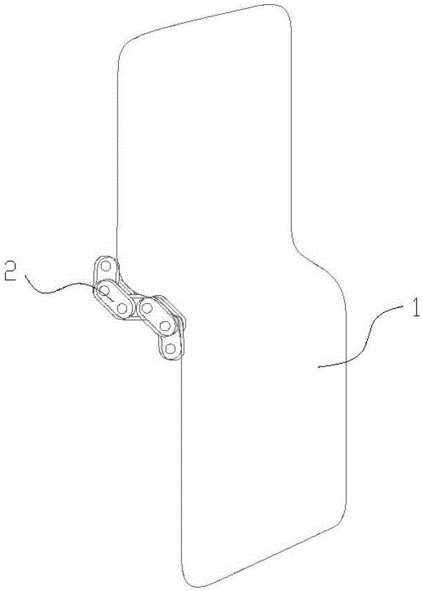
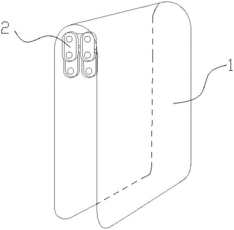
An electronic device and flexible technology, applied in branch equipment, electrical components, telephone communication, etc., can solve the problems of inconvenience of carrying, unable to meet the needs of users for flexible screen, increase in volume, etc., and achieve the effect of improving flexibility and convenient carrying method.

Inactive Publication Date: 2017-05-31
BEIJING XIAOMI MOBILE SOFTWARE CO LTD
View PDF5 Cites 14 Cited by
  • Summary
  • Abstract
  • Description
  • Claims
  • Application Information

AI Technical Summary

Problems solved by technology

[0002] At present, the application of electronic devices is quite common, and the edges of some electronic devices have been curved to improve the flexible touch of electronic devices. The multi-angle flip cannot meet the user's higher demand for flexible screens. Secondly, the user's demand for the screen size of electronic devices is increasing day by day, but a large screen will increase the size of the electronic device and make it inconvenient to carry.

Method used


Image

  • Flexible electronic equipment
  • Flexible electronic equipment
  • Flexible electronic equipment

Examples


Embodiment approach 1

[0032] figure 2 is a structural diagram of a rotating part shown according to an exemplary embodiment, image 3 It is an exploded view of the structure of the rotating part shown according to an exemplary embodiment, such as figure 2 , image 3 As shown, the rotating component 2 includes at least one rotating unit 21, and the rotating unit 21 includes a rotating shaft 22, a connecting piece 23 arranged in the middle of the rotating shaft 22, and structural members 24 arranged at both ends of the rotating shaft 22, The limiting mechanism is arranged on the rotating shaft 22 and abuts against the connecting member 23 and the structural member 24 respectively, and a locking member 25 for locking the structural member 24 is provided at the end of the rotating shaft 22 .

[0033] The connecting member 23 and the structural member 24 described in the present disclosure can adopt the same structure to facilitate mass production, and can also be designed into different structures ...

Embodiment approach 2

[0037] Figure 4 is a structural diagram of another rotating part shown according to an exemplary embodiment, Figure 5 is based on Figure 4 Another structural diagram of rotating parts is shown, such as Figure 4 , Figure 5 As shown, the rotating part 2 includes at least one rotating unit 31, and the rotating unit 31 includes a rotating shaft 32, a connecting piece 33 arranged in the middle of the rotating shaft 32, and a mounting device arranged at both ends of the rotating shaft 32. The structural member 34 of the hole 341, the limit mechanism is a clamping device arranged on the mounting hole 341 and the rotating shaft 32 to engage the structural member, and the end of the rotating shaft 32 is provided with a locking The locking member 35 of the structural member 34 .

[0038] It should be noted that the rotating shaft 32, the connecting member 33 and the structural member 34 in the second embodiment may adopt the same structure as the rotating shaft 22, the connecti...


PUM


Abstract

The invention provides flexible electronic equipment. The flexible electronic equipment comprises a flexible display screen and a rotating component connected to the flexible display screen, wherein a limiting mechanism is arranged on the rotating component; when the rotating component rotates to a target position under the external force, the limiting mechanism limits the rotating component at the target position, and the flexible display screen is in a bending state under the drive of the rotating component. The flexible overturning characteristic of the rotating component and the bendable feature of the flexible display screen are combined to realize forward overturning, reverse overturning and multi-angle overturning of the flexible electronic equipment, so that the flexibility of the flexible electronic equipment is improved, and a carrying way is more convenient.

Description

technical field [0001] The present application relates to the field of electronic equipment, in particular to a flexible electronic equipment. Background technique [0002] At present, the application of electronic devices is quite common, and the edges of some electronic devices have been curved to improve the flexible touch of electronic devices. The multi-angle flip cannot meet the user's higher demand for flexible screens. Secondly, the user's demand for the screen size of electronic equipment is increasing day by day, but a large screen will increase the size of the electronic equipment and make it inconvenient to carry. Contents of the invention [0003] In view of this, the present application provides a flexible electronic device. [0004] Specifically, the present application is achieved through the following technical solutions: a flexible electronic device, including a flexible display and a rotating part connected to the flexible display, the rotating part is ...

Claims


Application Information

Patent Timeline
Patent Type & Authority Applications(China)
IPC IPC(8): H04M1/02
CPCH04M1/0216H04M1/0268
Inventor 蔡杨洋
Owner BEIJING XIAOMI MOBILE SOFTWARE CO LTD
Learn More