
Online and intelligent optical cable monitoring and fault positioning system based on GIS platform

A technology for fault location and intelligent monitoring, applied in the transmission system, electromagnetic wave transmission system, structured data retrieval, etc., can solve the problems of test data inclusion, inconvenience, failure to complete fault location, etc., to achieve easy calculation, easy processing and storage effect

Inactive Publication Date: 2017-05-31
山西恒海创盈科技有限公司
View PDF7 Cites 47 Cited by
  • Summary
  • Abstract
  • Description
  • Claims
  • Application Information

AI Technical Summary

Problems solved by technology

[0007] However, the current fiber fault location still has the following problems: (1) OTDR test fiber is commonly used to obtain the optical power attenuation curves of multiple fibers, and then a computer is used for signal processing and analysis of a large amount of data, which is difficult for data processing. This directly leads to the inaccurate location of the calculated fault location in the fiber optic cable
(2) The data obtained by optical fiber monitoring of test data are all in text format, and there is such a problem in the detection method: the test data obtained by OTDR is mixed with a lot of noise, which increases the difficulty for personnel to determine optical fiber faults based on paper network topology and routing diagrams This method is very inconvenient; and non-professional optical cable maintenance personnel generally do not understand the network topology and routing diagram, and cannot complete the location of the fault location, resulting in extremely low maintenance efficiency
(3) The existing GIS map is not organically combined with the actual network routing of the optical cable, making it more difficult to determine the actual location of the fault point

Method used


Image

  • Online and intelligent optical cable monitoring and fault positioning system based on GIS platform
  • Online and intelligent optical cable monitoring and fault positioning system based on GIS platform
  • Online and intelligent optical cable monitoring and fault positioning system based on GIS platform

Examples


Embodiment

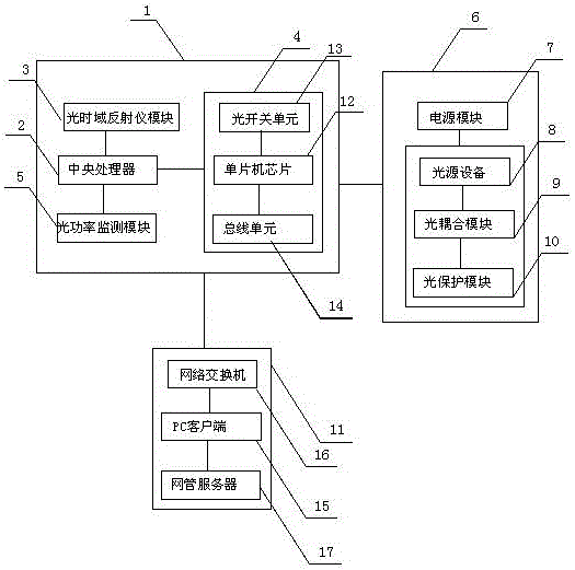
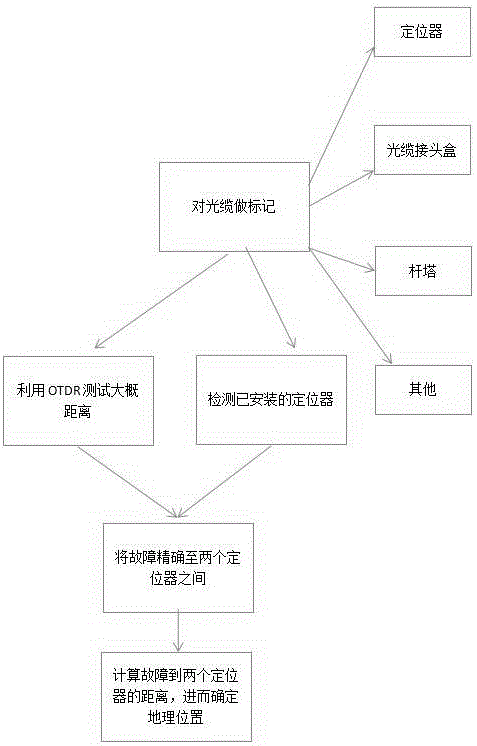
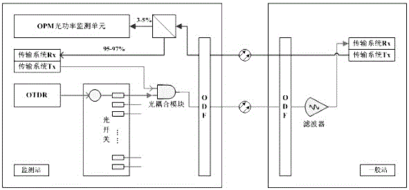
[0038] Such as Figure 1 to Figure 5 As shown, the optical cable online intelligent monitoring and fault location system based on the GIS platform includes a monitoring unit and a positioning unit. The monitoring unit includes an intelligent diagnosis host 1, a diagnosis unit 6 and a PC terminal display unit 11. The intelligent diagnosis host 1 includes a central processing unit 2 and the optical time domain reflectometer module 3, optical path switching module 4, optical power monitoring module 5 respectively connected to the central processing unit 2, and the diagnostic unit (OTDR) during the basic test, the pulse generated by the pulse generator drives the LD to generate The light pulse is injected into the optical fiber to be tested through the directional coupler. The light pulse injected into the optical fiber is scattered due to impurities, bubbles, etc. inside the optical fiber, and part of it is back scattered light (BACK SCATTERINGLIGHT), together with the FRESENL re...


PUM


Abstract

The invention provides an online and intelligent optical cable monitoring and fault positioning system based on a GIS platform. The online and intelligent optical cable monitoring and fault positioning system comprises a monitoring unit and a positioning unit, wherein the monitoring unit comprises an intelligent diagnosis mainframe, a diagnosis unit and a PC terminal display unit, the intelligent diagnosis mainframe comprises a central processing unit and an optical time domain reflectometer module, an optical path switching module and an optical power monitoring module connected with the central processing unit, the diagnosis unit comprises a power module and a light source device, an optical coupling module and an optical protection module connected with the power module, and the positioning unit comprises a fault locator arranged in an optical cable. Information is processed by calling optical cable information in time, and meanwhile the system can flexibly utilize a geographic information system (GIS) technology, adopts rack-type integration, and is high in integration level, good in stability and high in expandability. When breakdown occurs, the system can clearly display fault GPS points and fault types, maintainers can perform accurate positioning through a GIS map, and accordingly the maintenance efficiency is improved.

Description

technical field [0001] The invention relates to the technical field of power optical cable monitoring and troubleshooting systems, in particular to an online intelligent monitoring and fault location system for optical cables based on a GIS platform. Background technique [0002] The optical communication network is the most important communication network in the power industry at present, and it undertakes the construction of high-speed and long-distance backbone communication. With the continuous expansion of the optical network scale, the transmission structure of the network becomes more and more complex, and the maintenance of the optical cable and the monitoring of the status of the optical cable become more and more important and more complicated. The fiber optic cable built in the early stage has a certain number of years, and various hidden dangers and crises exist at any time. The increase in the number of fiber optic cable line failures year after year fully illus...

Claims


Application Information

Patent Timeline
IPC IPC(8): H04B10/071H04B10/079G06F17/30
CPCH04B10/071G06F16/29H04B10/0791
Inventor 张海峰
Owner 山西恒海创盈科技有限公司
Learn More