
On-off input circuit for relay protection testing device

A digital input and relay protection device technology, applied in the field of flat circuits, can solve problems such as damage to relay protection devices and lower work efficiency, and achieve the effect of reducing external connections

Active Publication Date: 2017-05-31
XIANGTAN UNIV
View PDF5 Cites 6 Cited by
  • Summary
  • Abstract
  • Description
  • Claims
  • Application Information

AI Technical Summary

Benefits of technology

This technology allows different inputs like numbers or characters to work better automatically regardless of their orientation on screen displays. Even when they're wrongly connected, this will still function properly. Additionally, by allowing certain signals from one direction into another direction through an electrode array instead of having them go backward, we don’t have any danger because these connections aren't possible during normal use. Overall, our technical effect is that this technology improves efficiency while minimizing risk factors associated with traditional methods such as cables connecting computers together.

Problems solved by technology

Technological Problem addressed in this patents describes how to efficiently troubleshoot relay protecting devices during maintenance without damaging them themselves when they fail due to incorrect connections between external components like cables.

Method used


Image

  • On-off input circuit for relay protection testing device
  • On-off input circuit for relay protection testing device
  • On-off input circuit for relay protection testing device

Examples


Embodiment Construction

[0018] The present invention will be further described below in conjunction with the accompanying drawings.

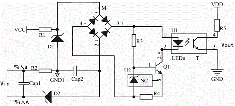
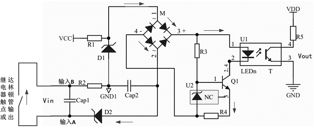
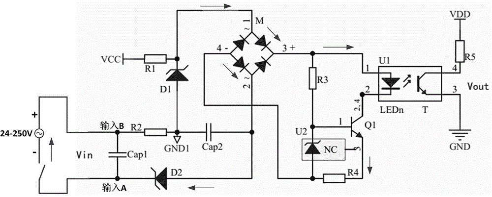
[0019] figure 1 It is the schematic diagram of the digital input circuit. VCC is connected to +12V power supply, VDD is connected to +3.3V power supply, and VCC and VDD do not share the same ground. +12V is connected to the cathode of 8.2V Zener diode (model ZPD8.2) D1 via 1K resistor R1, and the anode of D1 is connected to the ground GND1 referenced by +12V. Q1 is a triode FZT658 with a withstand voltage of 400V, U1 is a photocoupler PS2703, M is a bridge rectifier MB6S with a reverse withstand voltage of 600V, and U2 is a regulated power supply LM385M3 with a fixed voltage difference between the negative and positive electrodes of 1.2V , Zener diode D2 is ZPD5.1. In the normal state, the output of the circuit is in a high-impedance state, and the initial state of the rectifier bridge is in the bridge balance state, that is, the voltages of the AC input terminals (...


PUM


Abstract

The invention discloses an on-off input circuit for a relay protection testing device. The circuit consists of a voltage stabilizing diode, a rectification bridge circuit, a photoelectric coupler circuit, a triode switching circuit, a filter capacitor and a voltage stabilizing reference power circuit. The on-off input circuit for the relay protection testing device is self-adaptive about various types of the input patterns, and the pre-configuration does not need to be executed; and the on-off input circuit for the relay protection testing device is self-adaptive about the polarity of the active input, even the reverse connection can be correctly identified, and the potential safety hazard cannot be caused by the polarity of the input. The on-off input circuit for the relay protection testing device is provided with the potential output, and is capable of providing the power for the high-speed output of the Darlington tube type, and reducing the external connections.

Description


Claims


Application Information

Patent Timeline
Owner XIANGTAN UNIV
Learn More