
Efficiency optimizing control method for permanent magnet motor

A technology of permanent magnet motor and control method, which is applied in the direction of motor control, single motor speed/torque control, control system, etc., can solve the problems of increasing costs, reduce hardware circuit costs, improve product competitiveness, and be easy to implement Effect

Inactive Publication Date: 2017-05-31
中山瑞信智能控制系统有限公司
View PDF5 Cites 9 Cited by
  • Summary
  • Abstract
  • Description
  • Claims
  • Application Information

AI Technical Summary

Problems solved by technology

This control method will increase the cost for the application fields with strict cost requirements (such as home appliances), thus limiting the application of the simple sine wave control algorithm in these occasions

Method used


Image

  • Efficiency optimizing control method for permanent magnet motor
  • Efficiency optimizing control method for permanent magnet motor
  • Efficiency optimizing control method for permanent magnet motor

Examples


Embodiment Construction

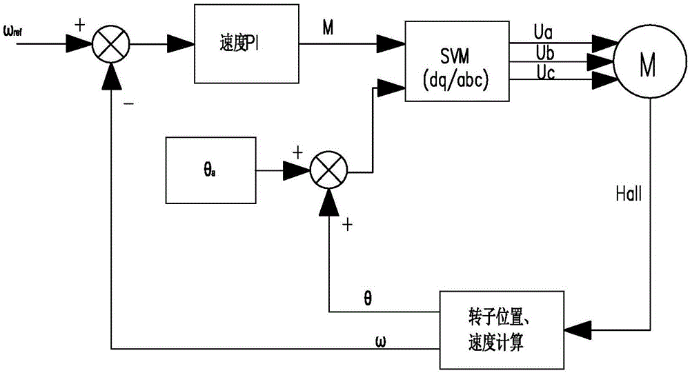
[0016] Such as figure 2 Shown, is the efficiency optimization control method of a kind of permanent magnet motor of the present invention, comprises the following steps:

[0017] (A) The Hall position signal of the motor rotor collected by the MCU through the capture port;

[0018] (B) Calculate the rotation speed ω of the motor and the angle θ of the rotor according to the Hall position signal;

[0019] (C) Set the given speed ω ref The difference between the motor's real-time rotation speed ω is calculated by the speed PI loop to generate the modulation ratio M of the sine wave;

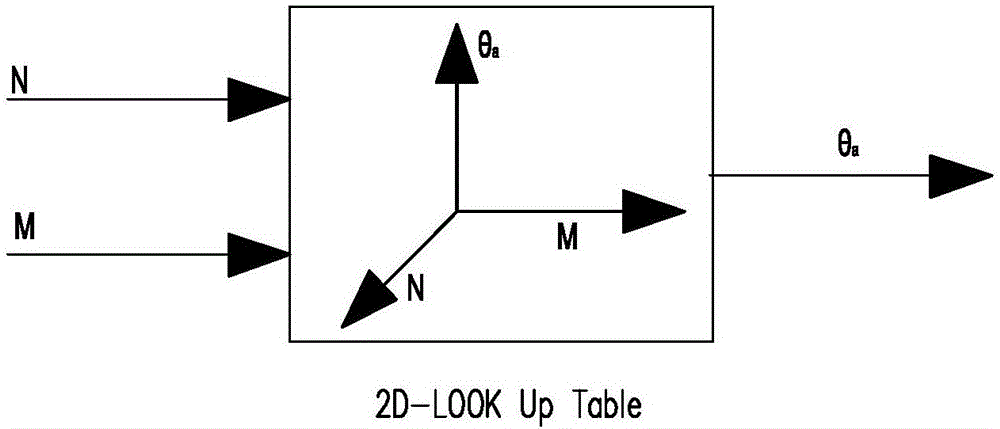
[0020] (D) Obtain the leading angle θ of the current vector lagging behind the voltage vector a ;

[0021] (E) Add the real-time angle θ of the rotor to the lead angle θ a Afterwards, SVM space vector modulation is carried out with the modulation ratio M of the sine wave to generate the sine wave drive signals Ua, Ub, and Uc required by the motor;

[0022] (F) Apply sine wave drive signals U...


PUM


Abstract

The invention discloses an efficiency optimizing control method for a permanent magnet motor. The efficiency optimizing control method comprises the following steps of (A) collecting a hall position signal of a motor rotor by an MCU through a capturing port; (B) working out a motor rotational speed <omega> and a rotor angle <theta> according to the hall position signal; (C) generating a sine wave modulation ratio M by performing calculation on a difference between a set speed <omega> <ref> and a real-time rotational speed <omega> of the motor through a speed PI ring; (D) obtaining a voltage vector advance angle which is as shown in the specification after current vector lagging; (E) adding the rotor real-time angle <theta> on the advance angle which is as shown in the specification, and then performing SVM (space vector modulation) with the sine wave modulation ratio M to generate sine wave driving signals U, U and U<c> required by the motor; and (F) loading the sine wave driving signals U, U and U<c> to the motor winding to enable the motor to rotate. By adoption of the efficiency optimizing control method, hardware circuit cost of the driver collecting phase current and vector decomposition parts is lowered, and product competitiveness is improved.

Description

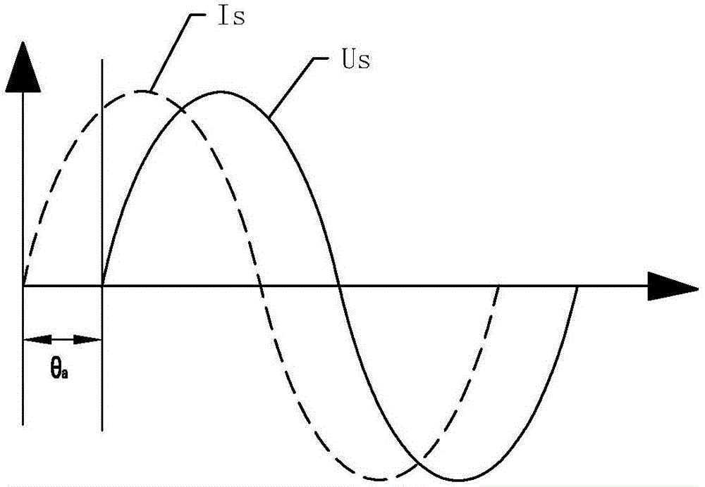
technical field [0001] The invention relates to the field of motor control, in particular to a simple sine wave control permanent magnet synchronous motor efficiency optimization control method. Background technique [0002] Because the motor is under different loads or speeds, the angle θ of the current vector lags behind the voltage vector a (referred to as the leading angle in this article) is not fixed, and the relationship between the three is difficult to analyze. Such as figure 1 As shown, is the back EMF and phase current of the motor winding. For the surface-mounted permanent magnet synchronous motor, the motor efficiency is the highest when the current vector Is and the back EMF voltage vector Us are in the same phase. Therefore, an algorithm is needed to adjust the angle of the current vector and the back EMF voltage vector in phase according to the current load and speed. If the angle θ of the current vector and the back EMF voltage vector can be known under th...

Claims


Application Information

Patent Timeline
IPC IPC(8): H02P6/08
CPCH02P6/08H02P2207/05H02P2209/11
Inventor 杨勇苏建中刘德超喻小勇
Owner 中山瑞信智能控制系统有限公司
Learn More